Ultrafast laser welding can join transparent materials to one another or to metals without adhesives or filler. This article explains the governing mechanisms, the main reliability bottlenecks, and the spatiotemporal beam-control strategies used to widen the process window.
High-rate heat accumulation Transparent-to-metal welding Burst mode Bessel beams
Application background
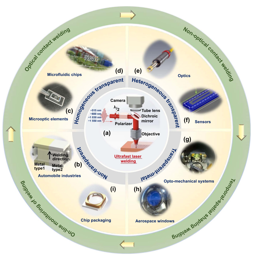
Advanced products often require glass, sapphire, fused silica, or another transparent material to be joined either to a similar substrate or to a metal or ceramic with high positional accuracy, strength, and hermeticity.
- Aerospace: hermetic attachment of optical windows to metal frames.
- Medical devices: microfluidic-chip packaging and hermetic sealing of implantable sensors.
- Consumer electronics: camera modules and optical components in AR/VR systems.
- Semiconductors: glass-lid packaging for chips and microsystems.
Limitations of conventional joining
Adhesives introduce several long-term risks:
- Aging and reliability: polymers can embrittle, yellow, or lose strength under time, heat, and ultraviolet exposure.
- Outgassing: organic molecules released in vacuum or clean environments may contaminate optics and sensitive components.
- Thermal stress and heat flow: an adhesive layer usually conducts heat poorly and may have a coefficient of thermal expansion far from that of glass or metal, generating stress during thermal cycling.
Anodic bonding is used mainly for silicon–glass systems and requires high temperature and voltage, which can damage sensitive electronics and restrict material choice.
Brazing and soldering add an intermediate material, another interface, and possible corrosion paths. Their high processing temperatures also create stress when the joined materials have very different thermal expansion.
Mechanical fasteners are bulky, concentrate stress, and rarely provide true hermeticity at small scale.
Why ultrafast lasers are different
- Highly confined processing: a femtosecond pulse lasts about \(10^{-15}\ \mathrm{s}\), much shorter than picosecond-scale electron–lattice energy exchange. Energy can be deposited locally with a small surrounding heat-affected zone.
- Nonlinear absorption: peak powers in the gigawatt or terawatt range trigger multiphoton absorption and tunneling ionization, allowing light to pass through a transparent surface and deposit energy at a buried interface.
- Direct fusion: no adhesive or solder is required. Local melting creates a strong, stable, potentially hermetic joint.
Core welding mechanisms
Homogeneous transparent materials: high-rate heat accumulation
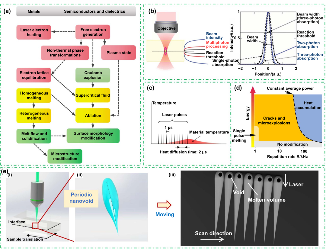
Step 1: initial energy deposition
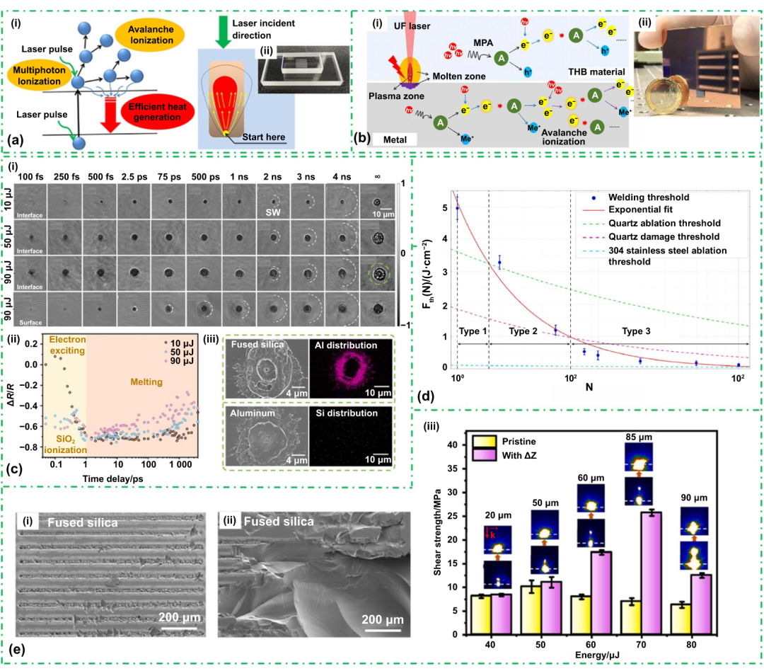
A femtosecond pulse is focused at the interface between two glass parts. When focal intensity exceeds roughly \(10^{13}\ \mathrm{W/cm^2}\), the strong electric field drives nonlinear absorption:
- a valence electron absorbs several photons through multiphoton ionization;
- the field narrows the potential barrier and enables tunneling ionization;
- the Keldysh parameter indicates which route is more important;
- seed electrons are accelerated and create additional carriers by collision, leading to avalanche ionization. The underlying mechanisms are developed further in Laser–Matter Interaction: Energy Absorption.
Step 2: from cold modification to thermal fusion
With a single pulse or a low repetition rate near 1 kHz, deposited energy diffuses away before the next pulse. The result is usually permanent focal modification or damage rather than a stable melt pool.
Welding relies on heat accumulation. Repetition rates generally exceed 100 kHz and may reach the megahertz range. The next pulse arrives before heat from the preceding pulse has fully diffused, so lattice temperature rises pulse by pulse until it exceeds the glass softening or melting range. Fused silica, for example, melts near 1700 °C.
In a representative case, a pulse interval of about 1 µs is shorter than a thermal-diffusion time near 2 µs, enabling sustained accumulation.
Step 3: formation of a tear-drop melt zone
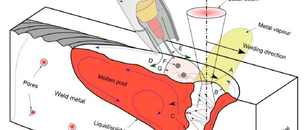
The modified or molten region often becomes tear-drop shaped. Once plasma forms around the nominal focus, it absorbs later energy strongly and changes beam propagation through refraction, reflection, shielding, and plasma defocusing. Effective deposition consequently shifts toward the incoming beam and extends axially. The plasma-heated zone grows until absorption, expansion, and cooling reach a balance.
After solidification, the cross-section is wider toward the incident side and narrower below. This tear-drop structure is the weld itself. A sound joint forms when it crosses the interface between the two transparent parts.
Transparent-to-metal joints: contact condition changes the mechanism
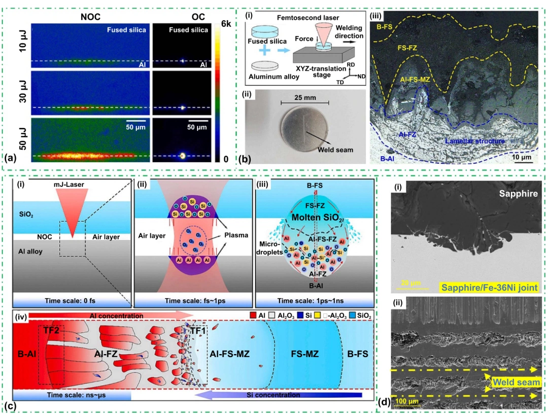
The beam first passes through the transparent member and reaches the transparent–metal interface. Free electrons in the metal absorb linearly and heat the surface rapidly. At sufficient intensity, the transparent side also undergoes nonlinear absorption.
Optical contact
The two surfaces are extremely flat and separated by less than approximately one quarter wavelength, commonly below 100 nm. Achieving this condition requires high-quality polishing and careful fixturing.
Metal vapor and plasma are confined inside the tiny gap, so temperature and pressure rise rapidly:
- the hot confined plasma transfers heat efficiently into the transparent material and melts it;
- high pressure drives the two melts to mix, penetrate, and react, sometimes creating alloyed or compound interfacial phases.
The joint is primarily metallurgical, and the source review reports strengths up to 108 MPa for favorable systems.
Non-optical contact
Industrial surfaces often contain micrometer-scale roughness and gaps. Plasma can expand freely, losing energy and pressure before it heats the transparent side sufficiently.
Joining then depends mainly on:
- molten-metal ejection and filling: droplets generated by ablation enter surface gaps under recoil and shock pressure, then solidify as mechanical anchors;
- reversible or irreversible expansion: at lower energy, softened transparent material expands into contact; at higher energy, melt ejection forces material into the gap.
Bonding is dominated by mechanical interlocking and van der Waals attraction and is commonly below 20 MPa. Reliable transparent-to-metal welding therefore begins with surface preparation and contact control. When optical contact is impractical, temporal and spatial shaping must compensate for the larger gap.
Confined plasma, high temperature and pressure, metallurgical bonding, and reported strengths up to about 108 MPa.
Free plasma expansion, gap filling and mechanical interlocking, commonly below 20 MPa.
Process bottlenecks
Mismatch in thermophysical properties
Coefficient-of-thermal-expansion mismatch is a central difficulty in dissimilar welding. Aluminum has a CTE near 23.6 ppm/K, roughly forty times the 0.59 ppm/K of fused silica. During cooling, aluminum contracts much more strongly, producing interfacial shear stress that can tear the weld or crack brittle glass.
Whenever possible, engineers choose low-expansion metals such as Invar or Kovar for glass joining. If the material pair cannot be changed, circular or segmented paths can distribute stress, while process parameters and cooling history are tuned to limit thermal gradients.
Melting-point and conductivity mismatch creates another imbalance. Metals often melt earlier and conduct heat much faster than glass or ceramics. The metal may melt or vaporize while the transparent member remains comparatively cold, making the interfacial state difficult to stabilize.
Uncertain interfacial products
An ideal interface mixes sufficiently or forms a beneficial reaction layer. In practice, results are material- and process-specific. Some steel–glass studies report no new phase, while aluminum–glass studies have identified alumina and nanoscale silicon.
The outcome depends on material combination, pulse conditions, gap, and cleanliness, and no general model yet predicts the reaction products reliably. Process development therefore still requires a carefully designed experimental window rather than a single transferable parameter set.
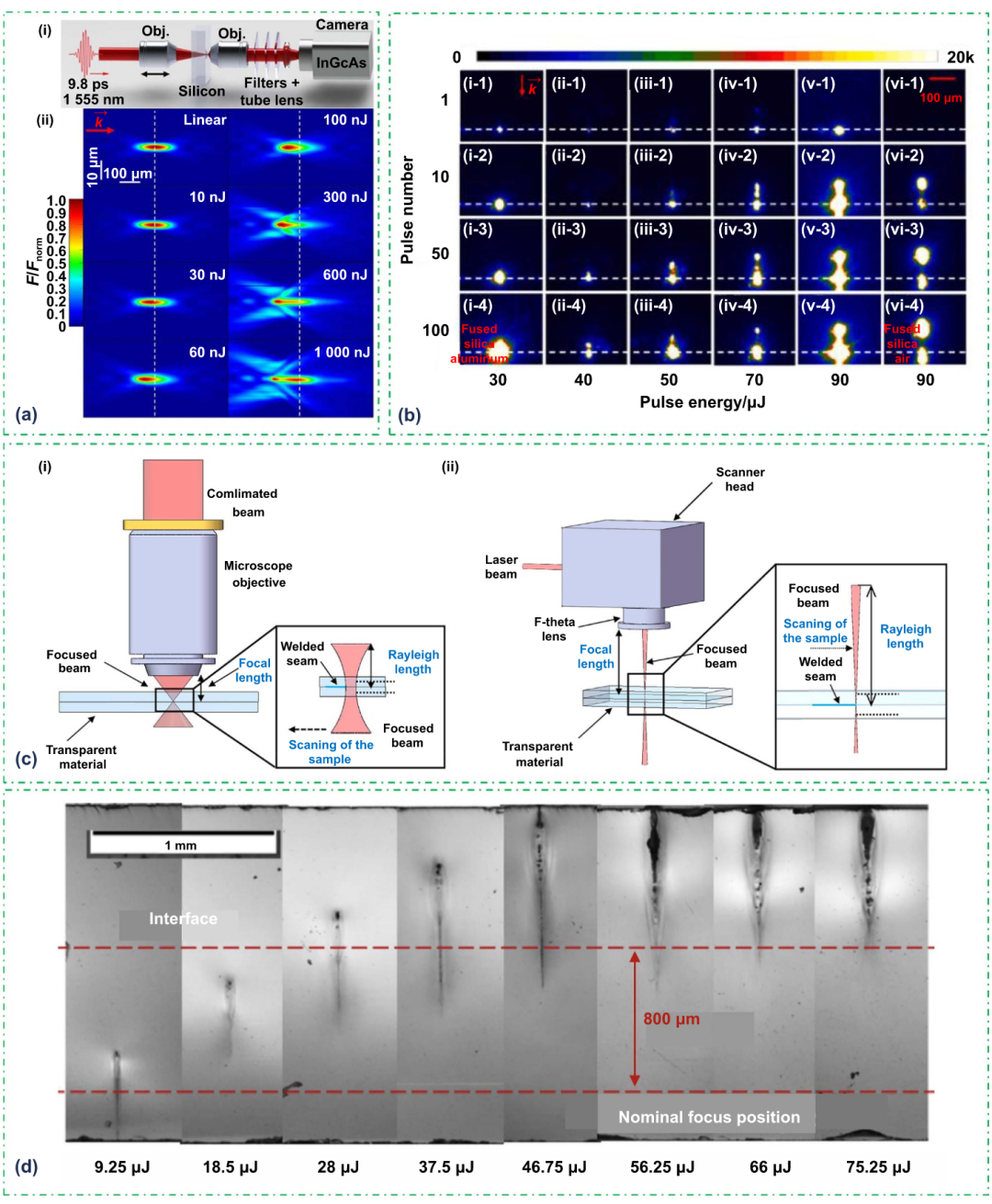
Focus drift
- Kerr self-focusing: high peak intensity raises refractive index and makes the material behave like a converging lens, moving the effective focus away from the geometric focus.
- Plasma defocusing: a plasma has a lower refractive index than the surrounding material and acts like a diverging lens.
Their competition makes energy deposition shift dynamically with pulse energy and accumulated carrier density. Consequences include:
- a narrow process window: the commanded focus no longer equals the optimum deposition point;
- weld inconsistency: small thickness or flatness variations produce local changes across a large path;
- depth error: the actual joining layer moves away from the intended interface.
Improving performance with spatiotemporal shaping
The governing idea is to control energy transport independently in time and space.
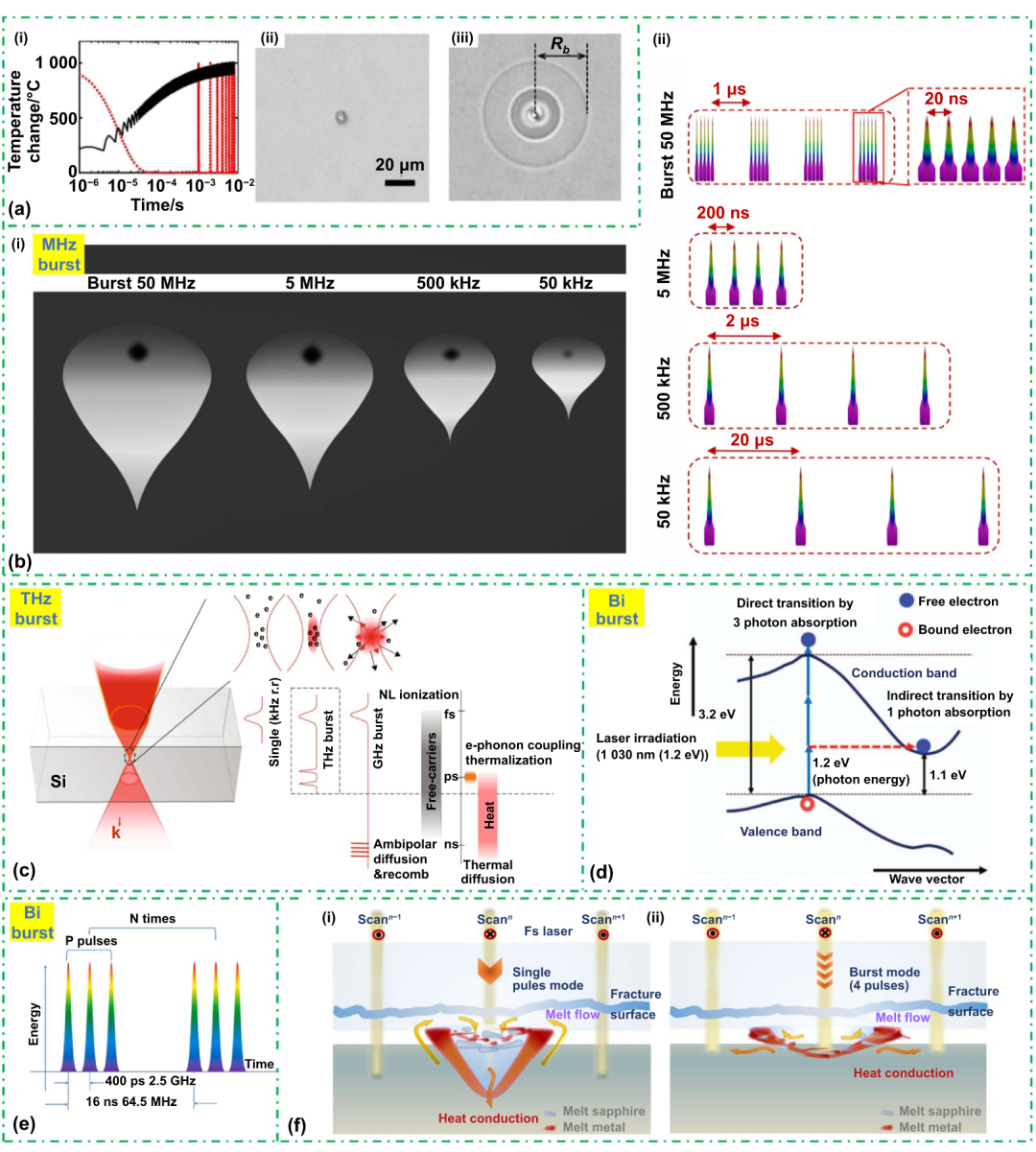
Temporal shaping: burst mode
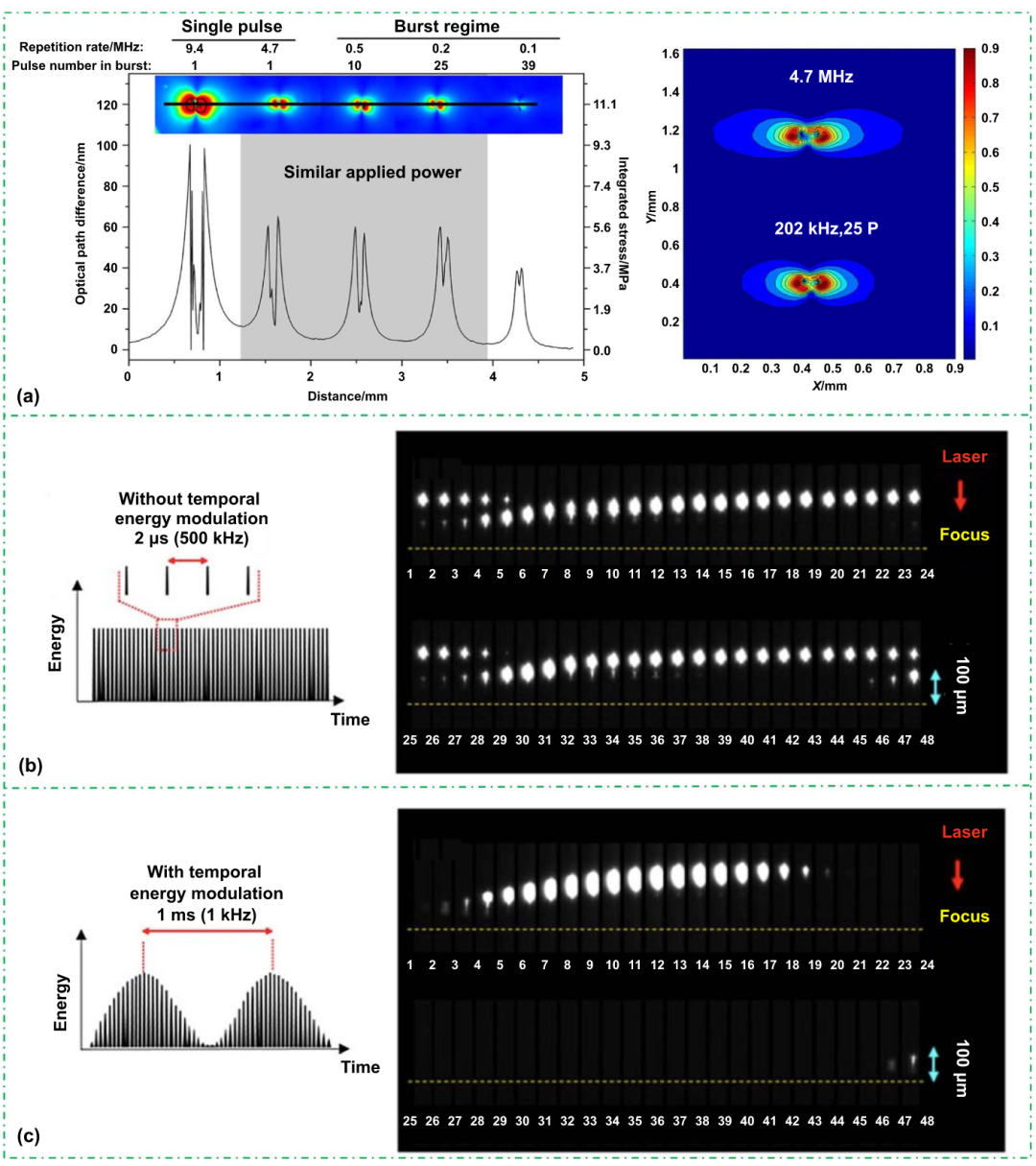
Continuous megahertz pulse trains accumulate heat efficiently but can also overheat plasma, steepen thermal gradients, and generate cracks.
In burst mode, a group of subpulses separated by nanoseconds forms one burst, while successive bursts are separated by a longer microsecond-scale interval.
- Efficient deposition: short intraburst spacing keeps the plasma active so later subpulses are absorbed efficiently and rapidly establish a melt.
- Controlled thermal relaxation: the longer interburst interval allows part of the excess heat to diffuse, reducing peak temperature, thermal gradient, and residual stress.
One example in the source review replaces a 9.4 MHz continuous train with a 100 kHz burst containing 39 subpulses. Penetration becomes shallower, but stress falls strongly and joint strength rises from 22% to 96% of the parent-material strength.
The burst envelope can also be shaped. Replacing a square envelope with a sinusoidal one produces gentler heating and cooling and further reduces thermal shock.
Spatial shaping: Bessel beams
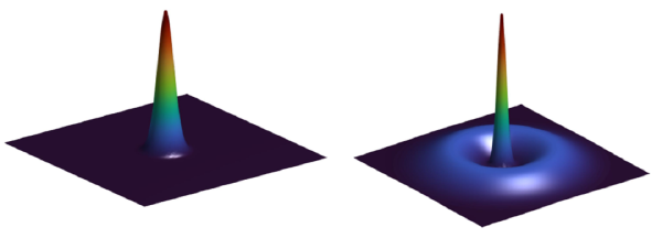
A Gaussian beam concentrates energy near one focus. A Bessel-like beam contains a narrow central lobe surrounded by concentric rings and can preserve the central lobe over a millimeter-scale axial range, producing a long effective depth of focus.
- Greater process tolerance: surface height error or fixture tilt of tens to hundreds of micrometers is less likely to move the interface outside the active zone.
- More stable deposition: a Gaussian beam heats mainly from one axial position, so upstream plasma can shield downstream material. Bessel energy converges conically from the side and supplies a longer volume, reducing shielding and producing a more uniform modification zone.
- Improved gap bridging: simultaneous melting over a long axial region helps upper and lower surfaces form a bridge across a non-optical-contact gap.
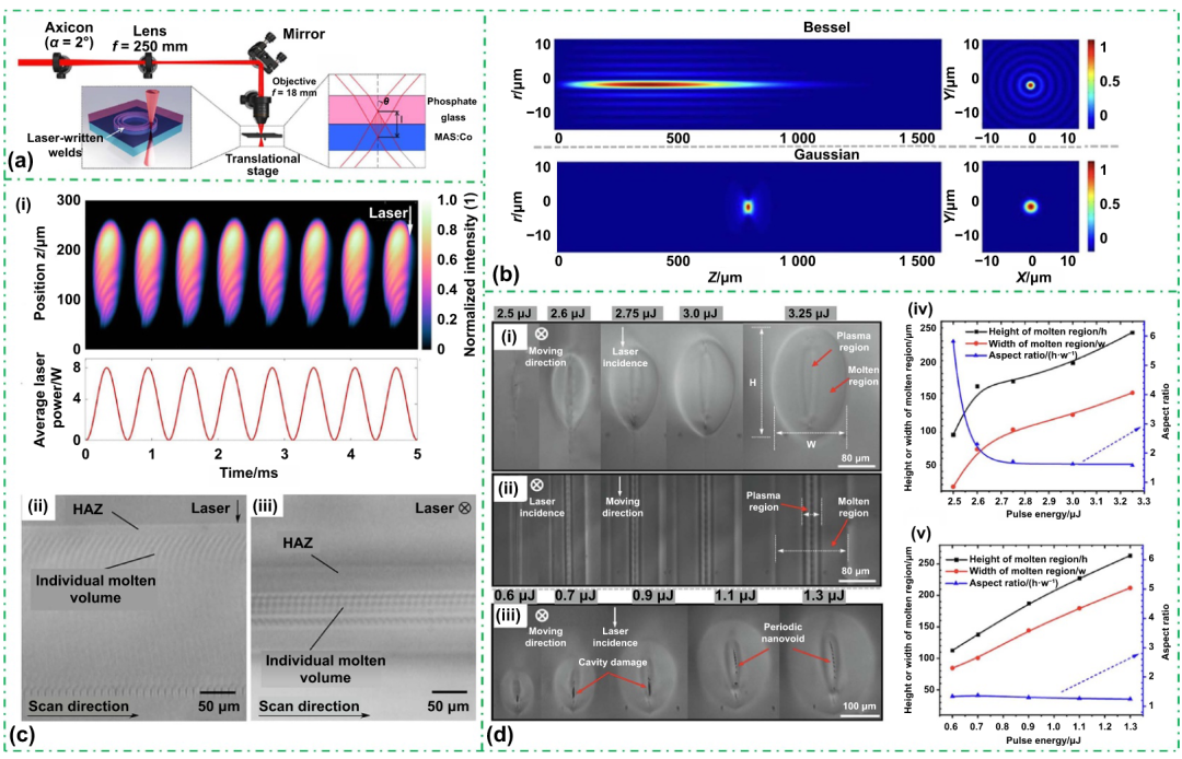
Combining burst mode and a Bessel beam is especially representative: temporal shaping manages heat and stress, while spatial shaping increases depth tolerance and stabilizes energy deposition.
Controls heat accumulation, heating and cooling rates, and residual stress.
Extends depth of focus, reduces shielding, and increases gap tolerance.
More uniform fusion, fewer voids, and a wider process window.
Applications
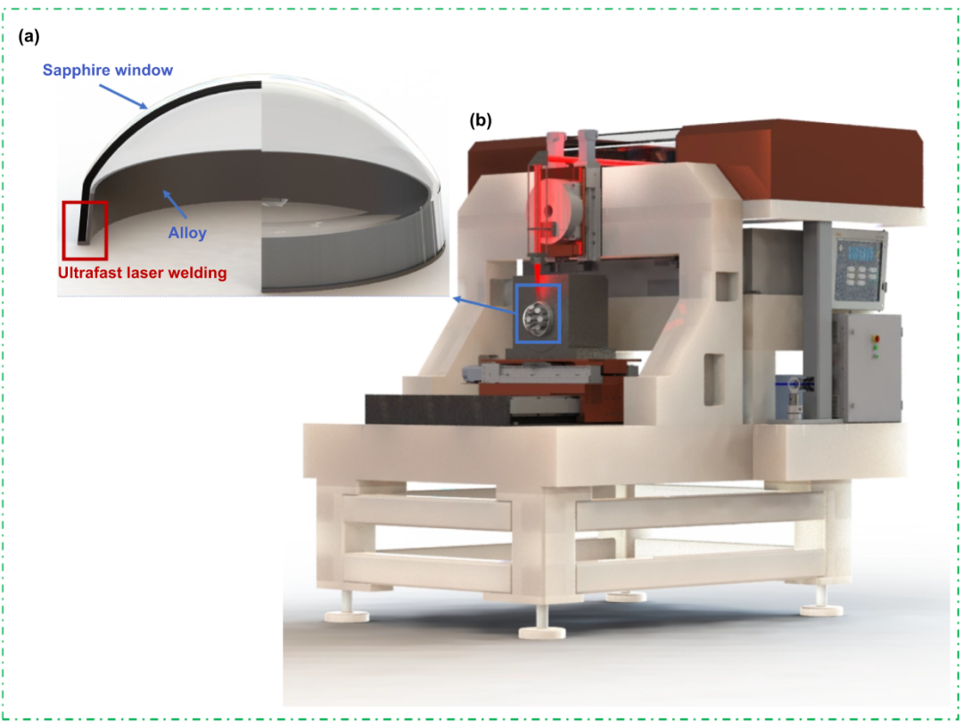
- Aerospace: joining sapphire windows to metal flanges with high strength and hermeticity; Bessel beams and closed scanning paths help maintain a continuous seal.
- Medical and biological devices: additive-free sealing of implantable pressure sensors and microfluidic chips, where a small heat-affected zone protects fragile channels and electronics.
- Automotive and consumer electronics: direct glass-to-metal joining for stronger, cleaner enclosures and optical assemblies.
Reference
- Jia, X., Luo, J., Li, K., Wang, C., Li, Z., Wang, M., Jiang, Z., Veiko, V. P., & Duan, J. “Ultrafast Laser Welding of Transparent Materials: From Principles to Applications.” International Journal of Extreme Manufacturing, 7, 032001 (2025). DOI: 10.1088/2631-7990/ada7a7.
The original Chinese edition was published by “Laser Insights” in Chongqing on June 17, 2025, at 07:25. View the original post