A weld inside a traction battery must carry high current while surviving vibration, thermal cycling, sealing loads, and long service. Starting from cell architecture, this article examines tab-to-busbar and enclosure joints and the control of Al–steel, Cu–Al, and Cu–steel dissimilar combinations.
Traction batteries Dissimilar materials Tabs and busbars Battery enclosures
Cell tabs, busbars, and enclosures
Al–Fe, Cu–Al, and Cu–Fe
Brittle phases, cracks, and pores
Heat input, interlayers, and beam modulation
Application background
Rapid growth in electric vehicles has made connection quality a battery-system concern rather than a local manufacturing detail. A pack contains many cells, links, busbars, terminals, and enclosure seams. A small increase in resistance, a cracked weld, or a leaking seal can reduce efficiency, shorten life, or create a safety hazard.
Conventional joining methods remain valuable but have boundaries:
- Ultrasonic welding creates a solid-state bond under pressure and vibration above roughly 20 kHz. It is effective for thin foil and conductive dissimilar materials, but the load and vibration can be difficult to apply safely to some cylindrical and prismatic structures.
- Resistance spot welding uses force and high current to create local heat. The high conductivity and thermal conductivity of copper and aluminum make stable localization more difficult.
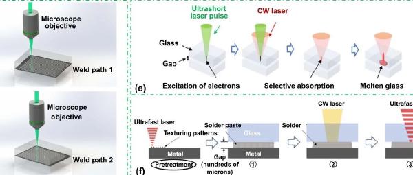
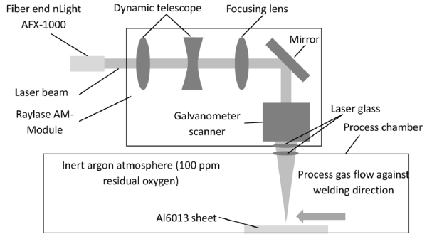
Laser welding is noncontact, concentrated, controllable, and readily automated. It can join Al–steel, Cu–Al, and Cu–steel tabs and busbars and can seal aluminum or stainless-steel enclosures.
The engineering goal is not merely to produce fusion. It is to balance low resistance, adequate strength, limited heat exposure, sealing integrity, and long-term reliability.
Cell formats and connection locations
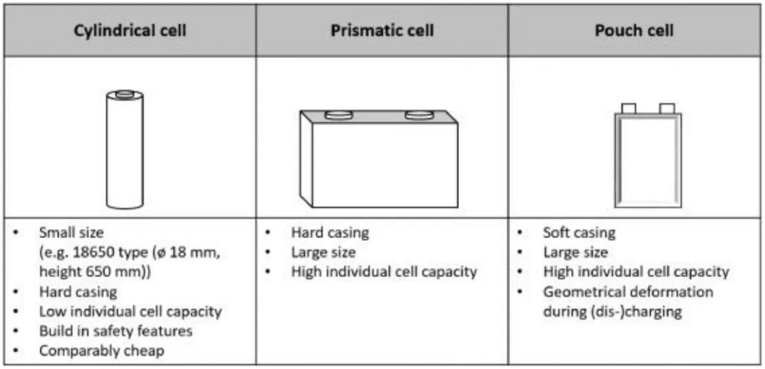
Three cell formats dominate:
| Cell format | Structural characteristics | Manufacturing focus |
|---|---|---|
| Small cylindrical | Highly standardized, economical, and mature safety design | Many cells and dense, highly consistent connections |
| Large prismatic | Rigid housing, large dimensions, high capacity per cell | Enclosure sealing, terminals, and busbars |
| Pouch polymer | Flexible package and high capacity; geometry may change during cycling | Thin-tab joining and strict heat control |
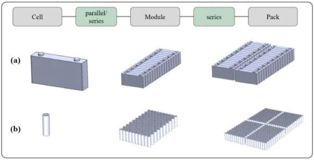
Cells are connected in series or parallel and then assembled into modules and packs. As the system grows, the number of joints and the range of service loads grow with it; connection quality becomes a system-level reliability variable.
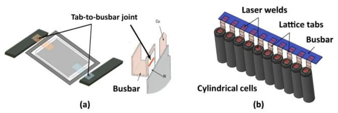
Welding tabs to busbars
Tabs are commonly aluminum, copper, or steel; busbars are usually copper or aluminum. A joint must provide mechanical retention and low resistance so that high-current cycling does not create a local hot spot.
Control the formation and thickness of Fe₂Al₅, Fe₄Al₁₃, and related brittle phases.
Suppress excessive growth of Cu₂Al, Cu₄Al₃, and other compounds.
Prevent copper penetration along steel-side grain boundaries and associated stress concentration.
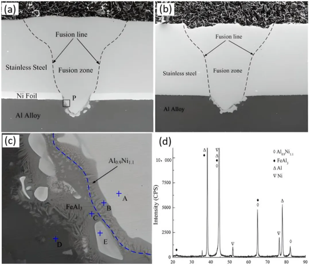
Aluminum to steel: keep intermetallics within an acceptable range
Large thermophysical differences and chemical affinity create brittle Fe–Al intermetallic compounds such as Fe₂Al₅ and Fe₄Al₁₃. Excessive reaction raises resistance and reduces strength, toughness, and service life.
Control methods include:
- Heat-input control: coordinate power, speed, pulse frequency, and duty cycle to balance penetration, HAZ width, and IMC growth. A ramped pulse can reduce temperature gradient and thermal stress.
- Interlayers: nickel or silicon-containing layers redirect interface reactions. Nickel can improve wetting and diffusion; silicon in an Al–Si layer changes Fe–Al compound growth. Even layers from several to several tens of micrometers can change the interface substantially.
- External fields: magnetic fields alter convection and elemental transport. Combined magnetic and ultrasonic assistance may refine grains, homogenize composition, and reduce pores and inclusions.
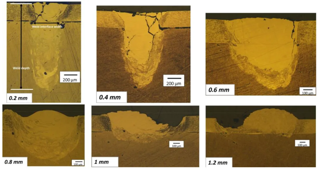
Copper to aluminum: limit direct reaction and redesign the interface
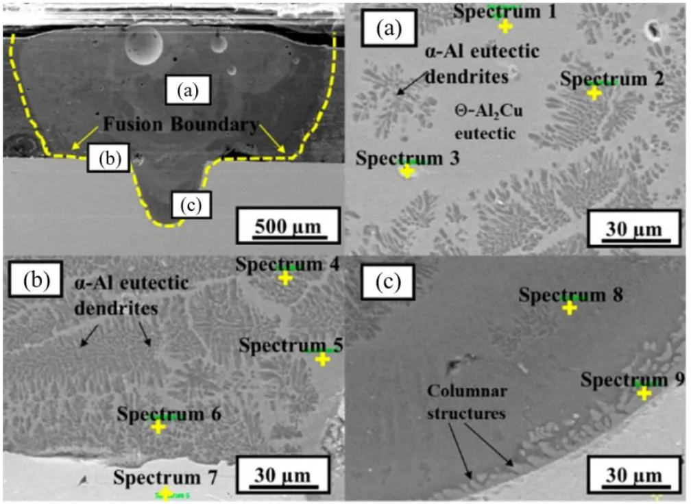
Copper and aluminum differ strongly in melting point, conductivity, and expansion and form several brittle compounds, including Cu₂Al and Cu₄Al₃. The process must reduce the duration and extent of direct high-temperature reaction.
- Parameter optimization: high speed and lower power shorten hot residence time; pulse frequency and duty cycle alter diffusion and compound-growth kinetics.
- Filler or interlayer materials: Ag-, Ni-, or Sn-based materials dilute the parent elements and redirect the reaction. Sn-containing filler, for example, may produce Cu₆Sn₅ and Cu₃Sn rather than an uninterrupted Cu–Al layer.
- Beam modulation: wobble, rotation, and beam splitting reshape energy and convection and therefore change mixing and solidification.
Copper to steel: use energy offset and oscillation against hot cracking
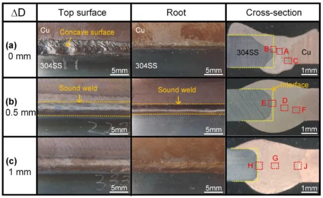
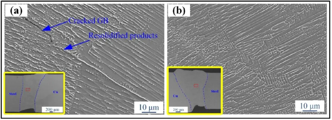
Cu–steel fusion can separate into compositionally different liquids and is susceptible to hot cracking, particularly when copper penetrates steel grain boundaries.
- Laser offset: position the spot away from the geometric seam to control how much of each material melts.
- Beam oscillation: circular motion redistributes heat and stirs the pool. Grain refinement increases boundary area, spreads strain, and improves resistance to cracking and distortion.
Battery-enclosure welding
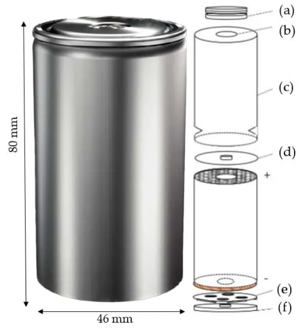
Enclosure seams provide both structural attachment and hermetic sealing. A cylindrical cell such as the Tesla 4680 contains several possible joining interfaces among can, cap, and current-collection components. Defects therefore threaten both mechanical integrity and electrochemical safety.
Aluminum enclosures: control pores and spatter
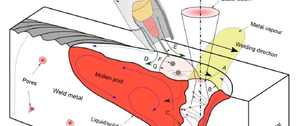
Aluminum’s high conductivity and expansion make cracks and pores common. Oxide and contaminants may decompose during welding, and gas is easily trapped by rapid solidification.
Two representative strategies are:
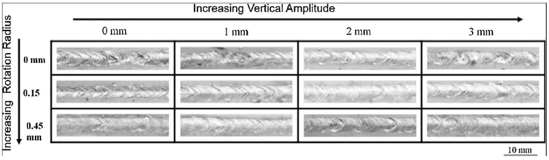
- Focused rotation and vertical oscillation: in 1060 aluminum, vertical oscillation improves the surface; a reported radius of 0.45 mm reduces porosity by 91%.
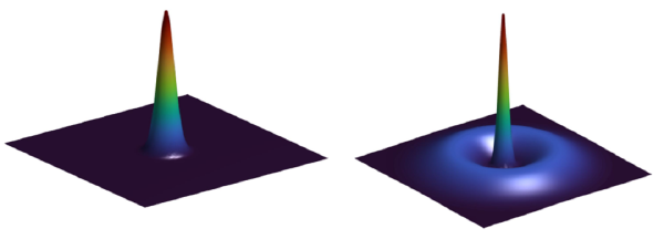
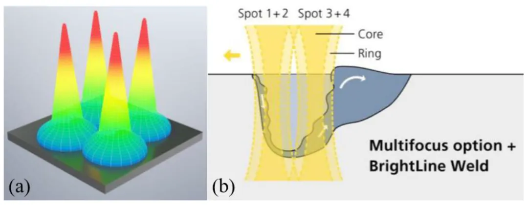
- Four-beam shaping: a distributed multi-spot field enlarges and stabilizes the keyhole, smooths vapor-pressure fluctuation, and reduces spatter and pores.
Steel enclosures: control hot cracking through heat input and solidification
Austenitic stainless-steel cans are vulnerable to hot cracking depending on chemistry, impurities, and solidification mode. Peak temperature, travel speed, beam trajectory, and shielding must be coordinated to avoid continuous low-melting boundary films and excessive tensile residual stress.
Engineering implications
Industrial welding commonly uses near-infrared wavelengths around 1064 nm. Blue or green sources can raise absorptance and widen the stable window for copper and aluminum.
No dissimilar-material recipe can be transferred without accounting for alloy, coating, surface state, fit-up, and equipment. A robust development sequence is to define electrical, mechanical, and sealing requirements; establish a heat-input window around the interface reactions; close the loop with cross-sections, IMC thickness, defects, and resistance; and only then add wobble, interlayers, or external fields for targeted correction.
Source material
This article is based on the Chinese “Laser Insights” review Laser Welding in Electric Vehicles: Traction Batteries. Technical figures and discussion primarily derive from:
- Junbo Feng, Peilei Zhang, Hua Yan, et al. Application of Laser Welding in Electric Vehicle Battery Manufacturing: A Review. Coatings, 2023, 13(8), 1313.
- DOI: 10.3390/coatings13081313
This page is intended for technical study; engineering decisions should use the original review and application-specific validation.