Laser cladding restores the geometry of a damaged landing-gear component. Laser shock peening, applied before and after deposition, modifies the interface and surface through grain refinement and residual compression, compensating for some of the performance loss created by the cladding thermal cycle.
30CrMnSiNi2A Laser cladding Laser shock peening Landing-gear repair
Create a refined layer and residual compression at the future interface.
Fill the damaged region and restore original geometry.
Deepen compression and refine the deposited surface.
Inspect fracture, hardness, EBSD, TEM, and bond quality.
Application background
30CrMnSiNi2A is a high-strength steel with useful strength, ductility, and toughness and is used for shafts, connectors, and heavily loaded aircraft landing-gear parts. Local damage and microcracks develop during service.
Laser cladding (LC) rebuilds lost geometry, but its thermal cycle introduces stress and may reduce mechanical performance. Laser shock peening (LSP) creates residual compressive stress and grain refinement. Combining the two provides a route to dimensional and mechanical restoration.
The study compares two routes:
Shock-peen the repair groove, deposit the clad, then peen the surface.
Deposit without groove pretreatment and peen only the finished surface.
The comparison isolates the contribution of groove pretreatment to interface quality.
Experimental parameters
Material and process
The substrate and powder are both 30CrMnSiNi2A. Principal composition ranges are C 0.27–0.34%, Cr 0.9–1.2%, and Ni 1.4–1.8%.
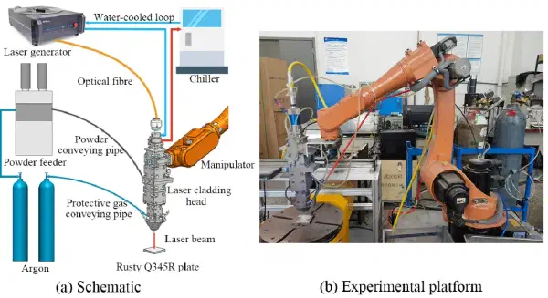
Laser-cladding parameters
- power: 0.8 kW
- travel speed: 8 mm/s
- overlap: 50%
- shielding: Ar
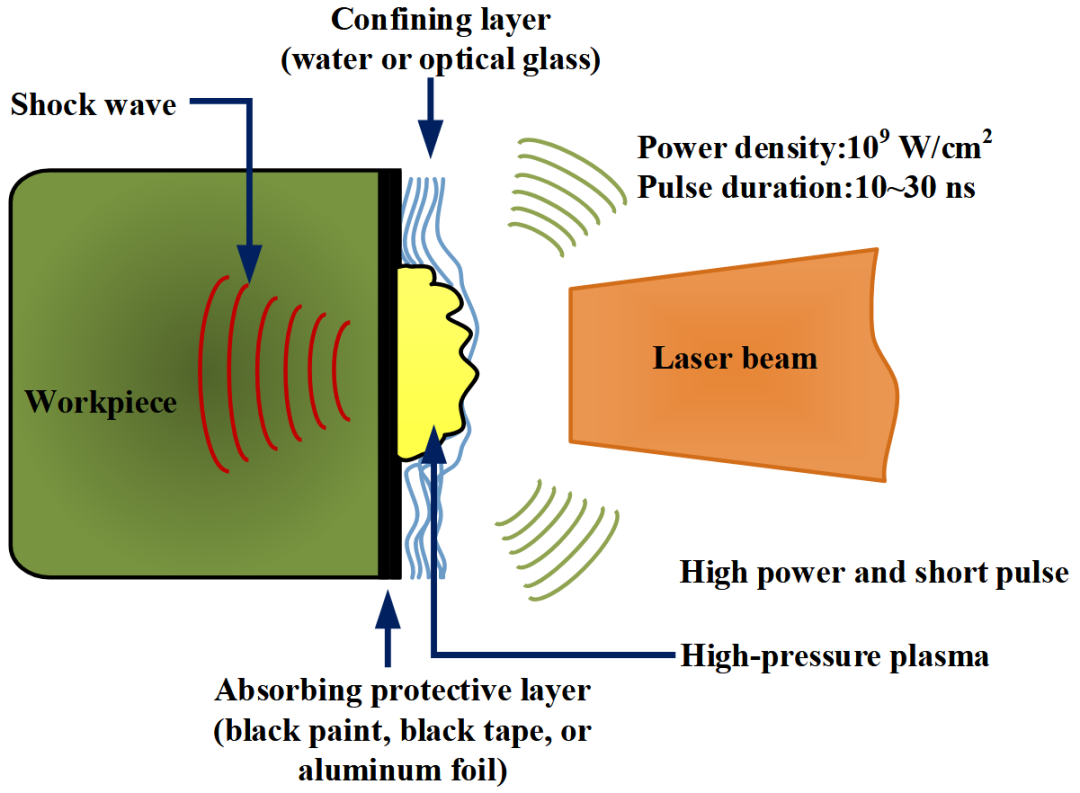
Laser-shock-peening parameters
- groove LSP: 2 J, 2 mm spot, 3.18 GW/cm²
- surface LSP: 3 J, 2.2 mm spot, 3.95 GW/cm², using higher energy for a deeper stress field
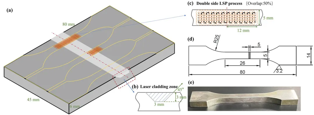
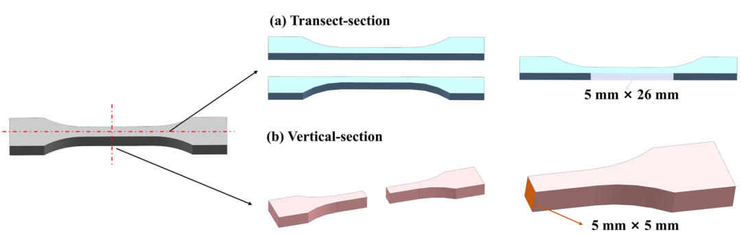
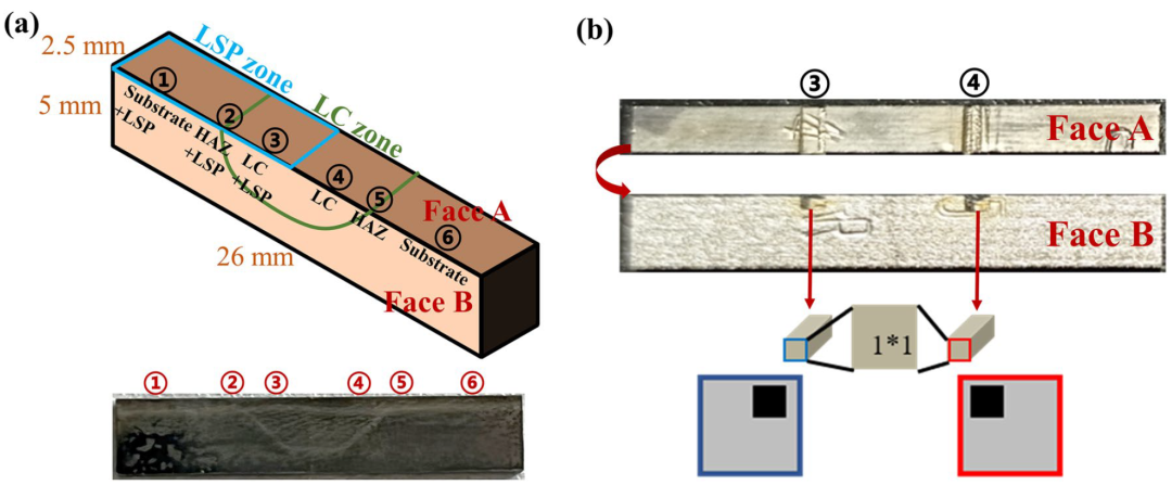
Core innovation: groove LSP and surface LSP
Why shock-peen the groove?
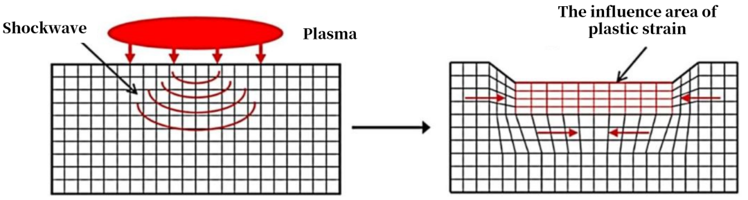
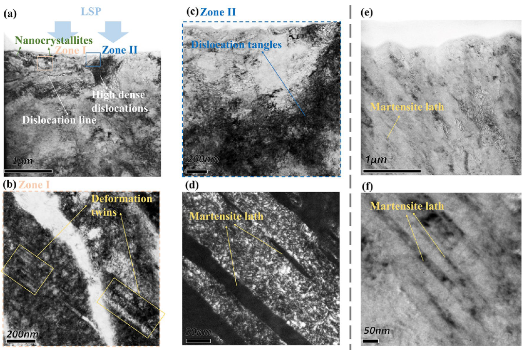
The groove becomes the clad–substrate interface, where conventional LC can leave microcracks under thermal stress. A 2 J groove treatment at 3.18 GW/cm² produces high dislocation density, grain refinement, and residual compression. During deposition, the pre-existing compressive state offsets part of the tensile thermal stress and improves interface strength.
The lower groove energy avoids excessive distortion that would reduce dimensional accuracy before deposition.
Surface LSP after cladding
A 3 J, 3.95 GW/cm² surface treatment serves two purposes:
- the residual-compression layer can extend beyond 1 mm, compared with approximately 0.2–0.5 mm for conventional shot peening;
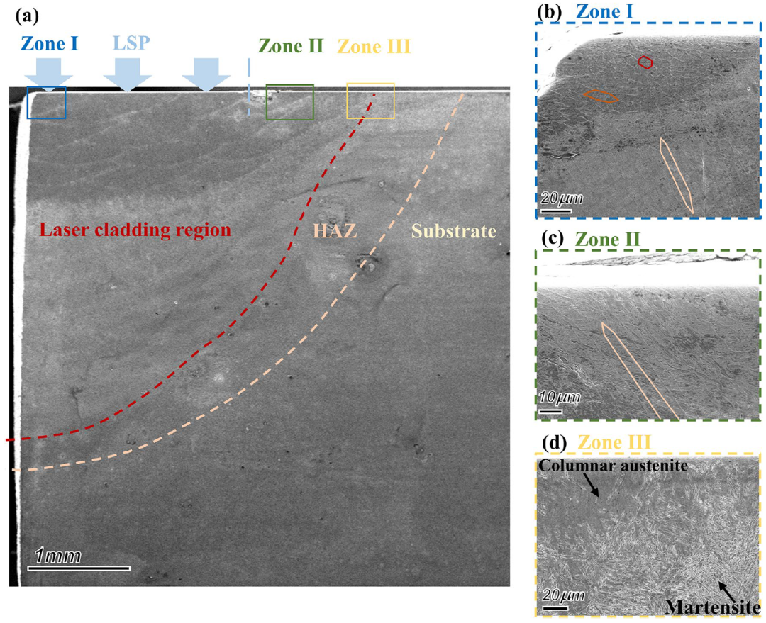
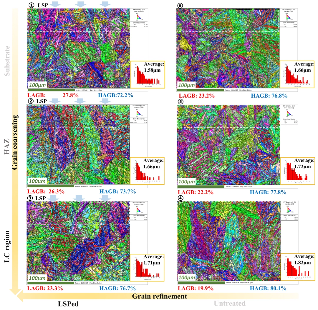
- columnar austenite grains approximately 30–40 µm are refined into 4–8 µm equiaxed grains, dislocation density rises, and hardness reaches approximately 800 HV₀.₂.
With and without groove pretreatment
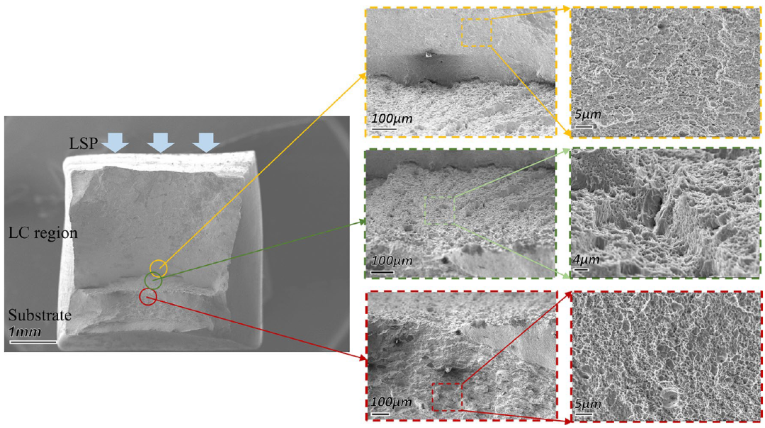
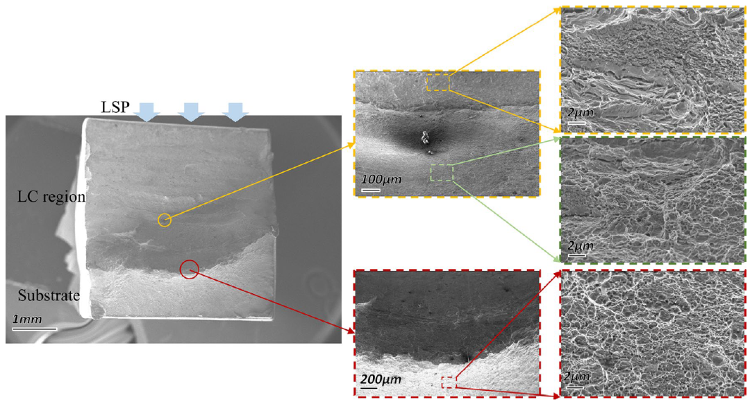
Without groove LSP, the clad–substrate interface remains the weak location and the fracture surface contains more pores. The groove-LSP specimen has a denser fracture and dimples closer to those of the substrate, indicating better bonding and ductile response.
Reproduction workflow
Step 1: substrate preparation
Machine a trapezoidal groove to match the damage depth, grind to Ra < 1.6 µm, and degrease with acetone.
Apply groove LSP at 2 J per pulse with 50% spot overlap. A single-spot trial should confirm that the surface does not ablate before full-area processing.
Step 2: laser cladding
- Vacuum-dry powder at 100–110 °C for approximately one hour, especially in humid environments.
- After each layer, forced-air cool toward 150–200 °C to limit heat accumulation and excessive austenite coarsening.
Step 3: surface LSP
- Begin with a 3 J single-pulse trial and measure the hardness gradient. Increase energy if the required hardness is not reached at 1 mm depth.
- Verify continuous coverage metallographically and adjust overlap if untreated gaps remain.
Engineering considerations
The “peen the groove, rebuild, then peen the surface” strategy addresses both interface and surface performance, but practical use has three constraints:
- Equipment cost: the study uses separate IPG YLS-2000 cladding and Nd:YAG peening systems.
- Geometric adaptability: uneven clad thickness changes effective peening depth, while curved surfaces make coverage and incidence harder to control.
- High-temperature stability: refined grains and dislocation structures may recover during service and reduce the strengthening effect.
The method is therefore best suited to high-value, low-volume repair where performance improvement justifies complex equipment and qualification.
References
- Wang, L., Yu, K., Cheng, X. et al. “Effect of Laser Shock Peening on Microstructure and Mechanical Properties of Laser Cladding 30CrMnSiNi2A High-Strength Steel.” Scientific Reports 13, 9971 (2023). DOI: 10.1038/s41598-023-37060-w.
- Cao, X.; Wu, J.; Zhong, G.; Wu, J.; Chen, X. “Laser Shock Peening: Fundamentals and Mechanisms of Metallic Material Wear Resistance Improvement.” Materials 17 (2024), 909. DOI: 10.3390/ma17040909.
The original Chinese edition was published by “Laser Insights” in Chongqing on March 10, 2025. View the original post. This page preserves the complete technical content, parameters, figures, conclusions, and references.