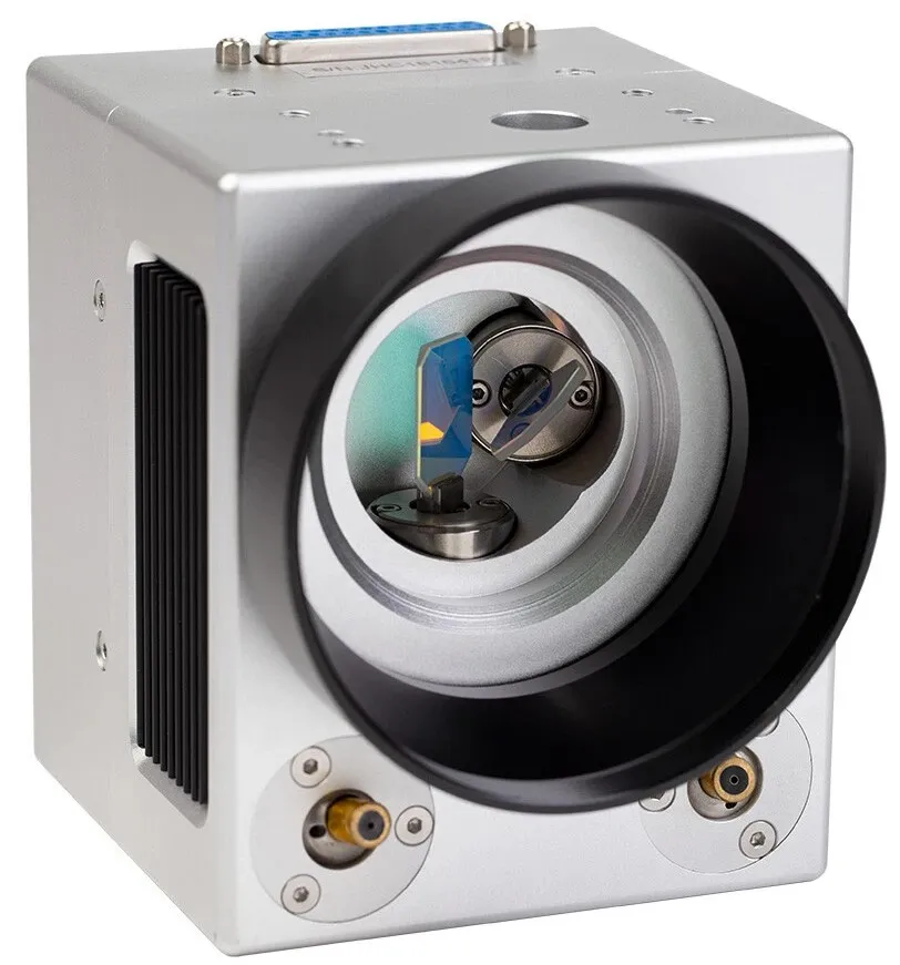
A galvanometer scanner is more than a pair of moving mirrors. It is a tightly coupled mechanical, optical, sensing, and control system that turns digital trajectories into high-speed, high-precision beam motion.
Beam steering Closed-loop servo Distortion correction Scanner–stage coordination
This article closes the original Laser Fundamentals series. The next articles move from laser-system fundamentals into laser applications.
Introduction
In precision laser technology, the galvanometer scanner is a central motion-execution unit. From millimeter-scale industrial marking to micrometer-scale additive manufacturing, its combination of speed and precision makes it essential in processing, imaging, and measurement systems.
Yet many laser-application engineers encounter the scanner as both familiar and opaque:
- How can corner overheating in laser additive manufacturing be eliminated at the control level?
- Why does traditional step-and-scan processing introduce stitching errors, and how does Infinite Field of View (IFOV) solve them?
- Why are small-aperture scanners fast while large-aperture scanners respond more slowly?
- Can command-following error be reduced proactively through feedforward control?
- How can a microsecond-scale positioning system remain stable while suppressing jitter and thermal drift?
These questions are connected by four physical and control relationships:
Speed favors low inertia, while power handling and beam quality favor a large clear aperture.
Feedback follows error; digital feedforward and look-ahead can anticipate the path.
Fast positioning must suppress both high-frequency disturbance and long-term thermal error.
Large-area processing requires coordinated allocation of low- and high-frequency motion.
Scanner fundamentals: how does it work?
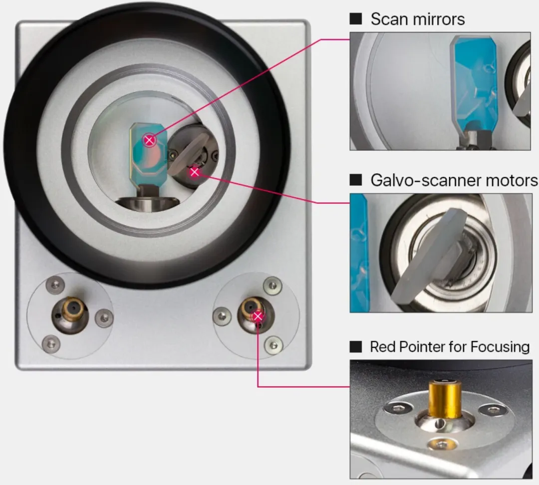
Everything begins with deflection
Laser scanning is fundamentally the precise, controllable deflection of a beam. Without deflection, a laser produces a stationary spot. With a scanner, the beam can be directed rapidly to arbitrary positions within the working field.
Three principal deflection technologies are used in industry:
| Technology | Speed | Deflection range and aperture | Addressing behavior |
|---|---|---|---|
| Rotating polygon mirror | Extremely high | Can handle comparatively large beams | Usually periodic one-dimensional raster scanning |
| Acousto-/electro-optic deflector (AOD/EOD) | Nanosecond response | Limited angle and aperture | No mechanical inertia; ideal for ultrafast small-range scanning |
| Galvanometer scanner | High | Broad choice of apertures and fields | High-precision flexible two-dimensional vector addressing |
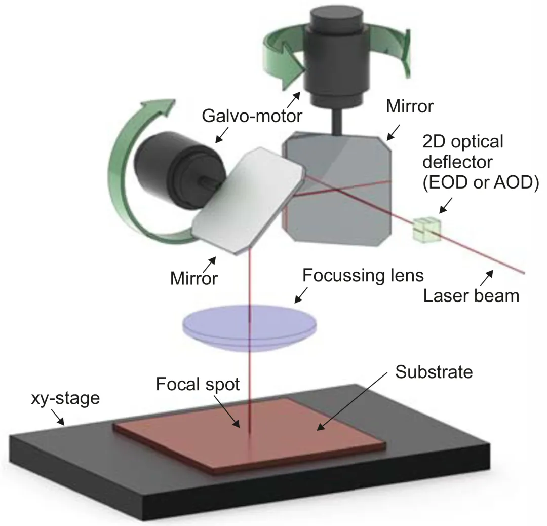
Oscillating motors and Lorentz force
At its core, a galvanometer scanner is a precision oscillating motor. A current-carrying coil in a permanent magnetic field experiences a torque proportional to current through the Lorentz-force mechanism.
The principle resembles an electrical galvanometer. In a meter, the coil moves a pointer so that angle represents current. In a laser scanner, a high-reflectivity mirror replaces the pointer. The drive electronics convert an input command into controlled coil current. The mirror does not rotate continuously; the servo moves it rapidly and holds it at the commanded angle.
Two axes create a two-dimensional scan plane
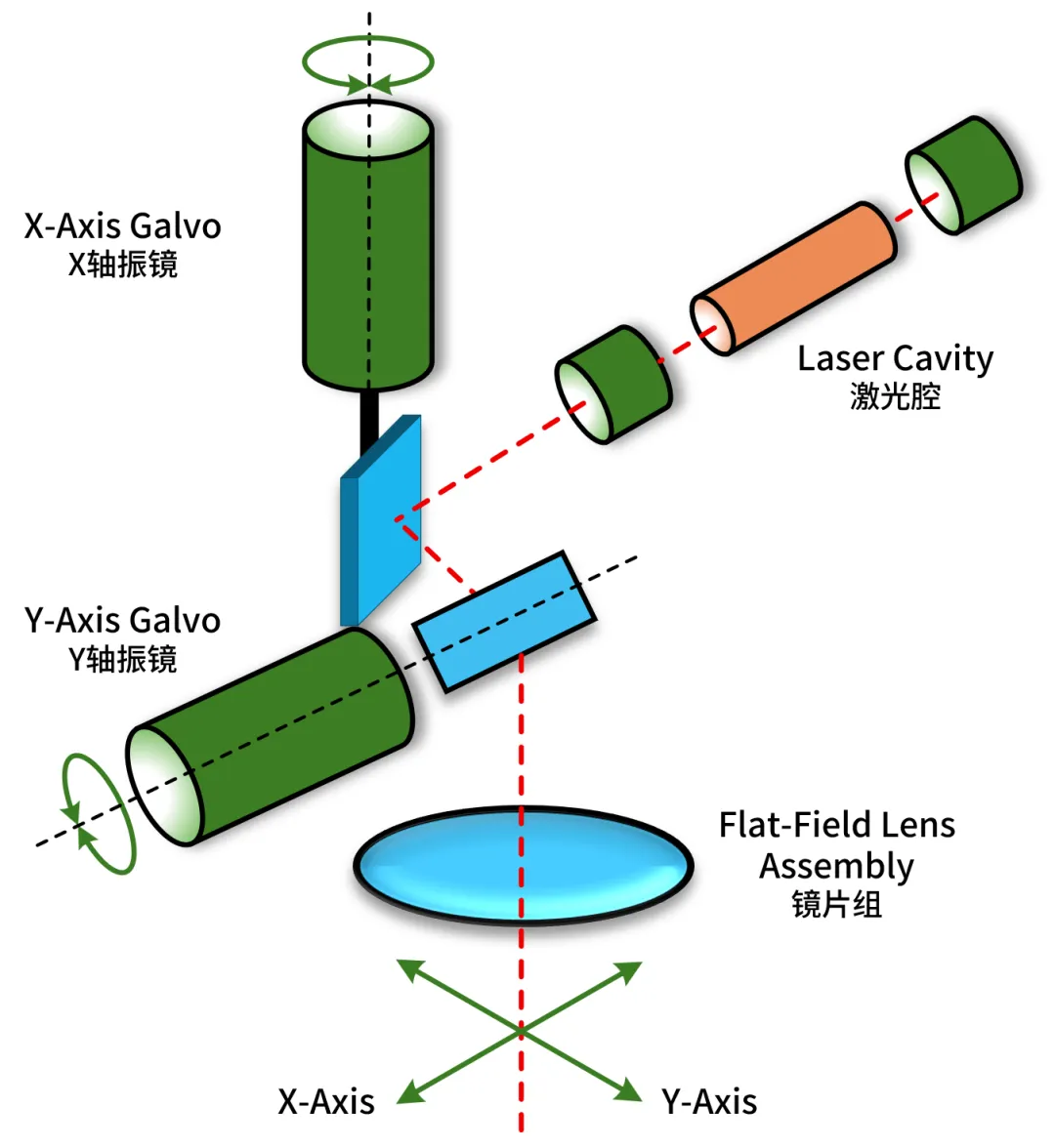
A typical two-dimensional scan head uses two galvanometers with orthogonal rotation axes:
- the beam first strikes the X-axis mirror;
- the reflected beam then strikes the Y-axis mirror;
- the computer controls the two angular positions independently;
- the spot can be directed to any \((X,Y)\) coordinate in the working plane.
This vector-based random addressing is the main advantage of galvanometers over raster-oriented systems such as polygon scanners.
Jumping and marking
Scanner motion is normally divided into two states according to laser emission:
- Jump motion: the laser is off while the scanner repositions. Because no processing occurs, the scanner generally uses the highest permitted velocity and acceleration;
- Marking motion: the laser is on. Velocity must be controlled according to line energy, contour quality, melt-pool stability, or another process requirement.
The central trade-off: speed versus clear aperture
High speed requires sufficient motor torque and very low rotational inertia in the mirror, shaft, and rotor. Lower inertia enables faster acceleration and settling.
High power and preserved beam quality require a large clear aperture so that the full beam reaches the workpiece without clipping. This is especially important in high-power systems.
The requirements conflict directly: a larger mirror has greater mass and rotational inertia. That is why no universal scan head exists. Commercial products cover apertures from roughly 3 to 50 mm and beyond:
- Small-aperture scanners: low inertia and high dynamic speed for small beams and fast applications such as biomedical imaging;
- Large-aperture scanners: slower response but the ability to carry large, high-power beams for welding, cutting, and additive manufacturing.
Scanner selection is therefore an engineering trade-off between dynamic performance and optical power-handling capability.
The complete galvanometer-scanning system
A high-performance scanner is not just a motor and mirror. The system combines the source, beam conditioning, scanning, focusing, and control layers.
System architecture
A typical optical and control chain is:
Generates a beam with the required wavelength, power, and temporal behavior.
Collimates and enlarges the beam while reducing divergence.
Convert digital commands into two-dimensional angular deflection.
Focuses, flattens the field, and approximately linearizes scanning.
Receives the focused spot along the programmed path.
The controller and software synchronize scanner position, laser gating, and laser power, completing the chain from digital geometry to physical processing.
Galvanometer motor
The motor determines dynamic performance through its rotor/stator design and bearings.
Stator and rotor:
- Moving-magnet design: the magnet is the rotor while the coil remains stationary. This is common in high-performance scanners because the rotor is simple and low-inertia, supporting a higher resonant frequency and faster response;
- Moving-coil design: the coil rotates while the magnet remains fixed. Torque efficiency can be high, but coil mass and volume increase rotor inertia and limit maximum response.
Bearings: high-quality precision ball bearings with axial preload provide zero backlash, high stiffness, low friction, and long life.
Scanning mirrors
The mirrors determine optical quality and power handling:
- Aperture: the effective clear diameter and therefore the maximum beam diameter;
- Silicon substrate: good thermal conductivity and stiffness, commonly used in medium- and high-power infrared systems such as CO₂ and fiber lasers;
- Fused-silica substrate: extremely low thermal expansion and low deformation with temperature, preferred for ultraviolet and ultrafast systems where thermal lensing and focus drift must be minimized;
- Coating: multilayer dielectric stacks designed for a specific wavelength, typically providing reflectivity above 99.5%.
F-Theta lenses: flat-field focusing and linearization
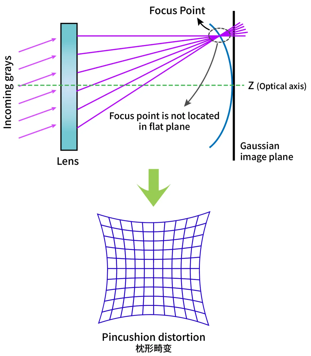
Without an F-Theta lens, two serious problems appear:
Field curvature: an ordinary focusing lens focuses the scanned beam onto a curved surface rather than a plane;
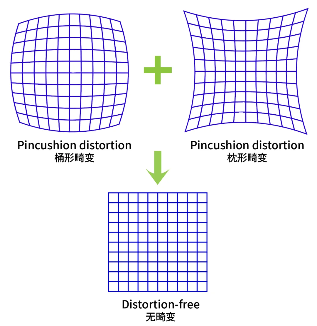
Nonlinearity and pincushion distortion: the displacement \(y'\) at a plane follows
\[ y'=f\tan(\theta) \]rather than a linear relationship. Constant angular velocity then produces a spot that moves faster near the edge than near the center. Energy density becomes nonuniform and a commanded square can become pincushion-shaped.
An F-Theta lens is a specially designed lens group that deliberately introduces barrel distortion to counter the scanner’s pincushion distortion and make displacement approximately linear with angle:
\[ y'\approx f\theta \]Its main functions are:
- Scan linearization: approximately constant spot velocity for constant mirror angular velocity;
- Flat-field focusing: focus is maintained across the scan field;
- Spot consistency: spot size and energy density remain as uniform as possible across the field.
Beam expanders: trading a larger beam for lower divergence
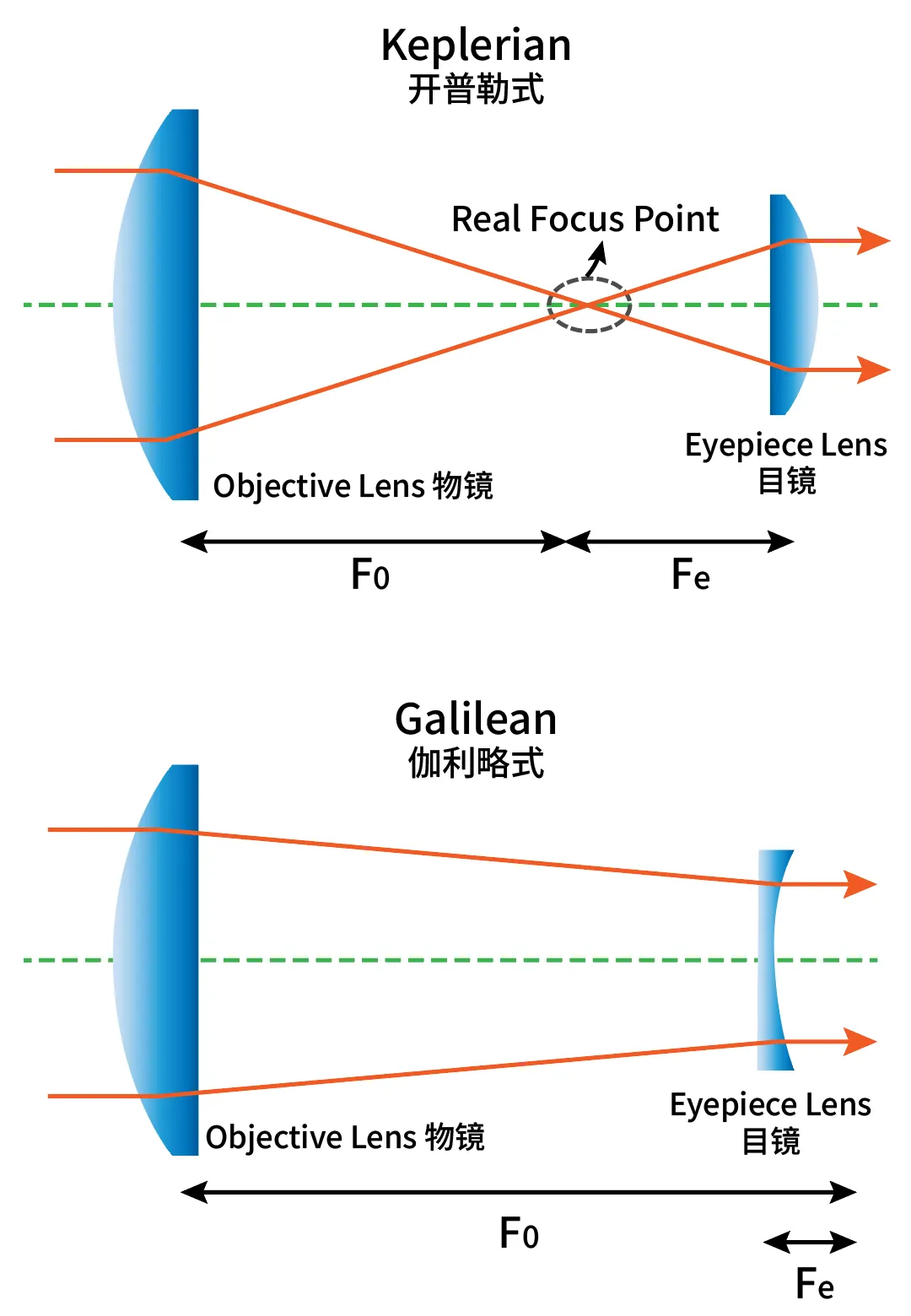
A beam normally passes through an afocal beam expander before entering the scanner. If its diameter is increased by a factor \(M\), far-field divergence is reduced to
\[ \frac{1}{M} \]Because focal spot size is closely related to incident divergence, lower divergence supports a smaller focus and higher processing resolution.
- Keplerian expander: two positive lenses create an internal real focus. It supports spatial filtering, but the internal focus can cause air breakdown at high power;
- Galilean expander: one negative and one positive lens, no internal focus, and a compact structure. It is the most common industrial design.
Closed-loop servo control
Scanner speed and precision depend on a fast, accurate closed-loop servo.
Why closed loop is essential
- Open loop: sends commands without measuring the result, so actual position cannot be corrected for drift, load, or disturbance;
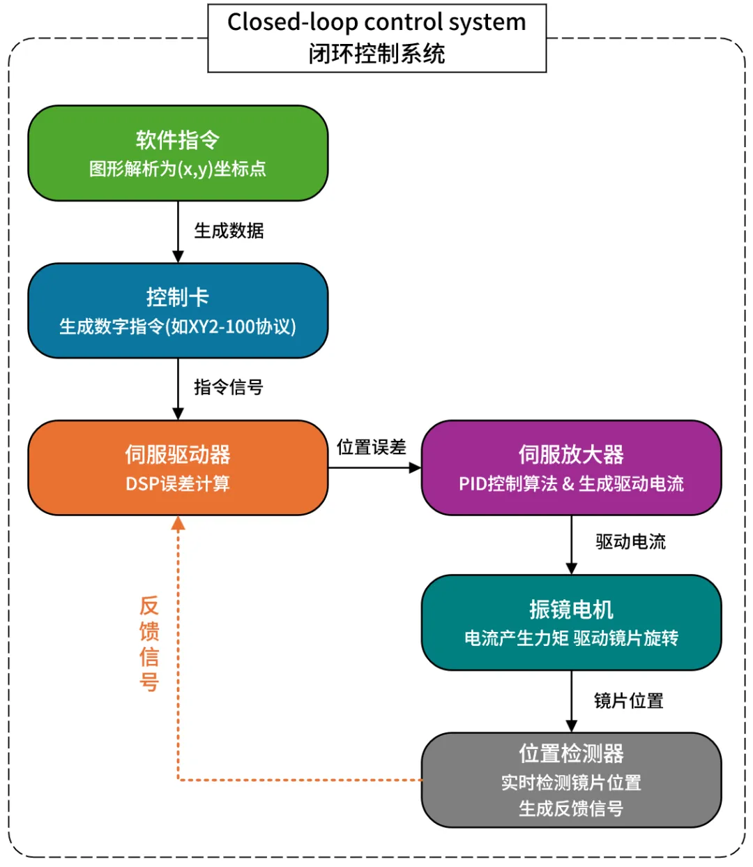
- Closed loop: continuously compares the commanded position with the measured position. Their difference is the position error, and the controller drives that error toward zero.
From digital command to mirror angle
One control cycle contains six steps:
- Software command: geometry is converted into a sequence of \((X,Y)\) targets;
- Controller processing: an RTC-class control card transmits digital commands through a protocol such as XY2-100;
- Error calculation: the servo drive receives command and position feedback and calculates instantaneous position error;
- Drive-current generation: a servo amplifier uses PID or another control law to produce coil current of the required magnitude and direction;
- Motor deflection: large error produces high current and rapid motion; as error shrinks, current is reduced to settle with low overshoot;
- Feedback update: the position detector measures the new angle and begins the next cycle.
The command–feedback–error–drive loop repeats thousands or tens of thousands of times per second.
Position detectors
The position detector is the critical sensor in the servo and directly influences accuracy, resolution, and stability.
- Optical analog detector: an infrared LED illuminates a vane on the shaft; changing shadow distribution on a photodiode array is converted into angle through differential current;
- Capacitive analog detector: measures capacitance that varies with rotor angle;
- Digital optical encoder: a high-resolution grating disk and read head produce a digital angle signal with high positioning accuracy, high resolution, and low long-term drift.
From analog to digital servo control
Limitations of analog control:
- susceptibility to electromagnetic interference and noise;
- manual potentiometer tuning and recalibration after component replacement;
- fixed control logic that is difficult to extend.
Advantages of digital control:
- high-speed DSP implementation of control algorithms;
- noise-resistant digital protocols such as XY2-100;
- model-based feedforward and path look-ahead in addition to PID feedback.
The conceptual difference is important. An analog servo is typically reactive: it sees an error and then chases the command, so tracking error is unavoidable. A digital servo can use a plant model and known future trajectory for predictive control, reducing dynamic tracking error and approaching zero error under defined operating conditions. This capability is foundational for eliminating process defects such as corner overheating in additive manufacturing.
Key performance metrics
A scanner cannot be described only as “fast” or “accurate.” Speed, precision, and stability must be evaluated together.
Speed metrics
- Marking or writing speed: commonly specified in \(\mathrm{mm/s}\) or characters per second and directly related to productivity;
- Jump speed: repositioning speed with the laser off and a major contributor to nonprocessing time;
- Step response time: time required to complete a specified angular step and settle inside the tolerance band. Shorter settling improves throughput.
Precision metrics
- Accuracy: agreement between commanded and actual position across the full scan field;
- Repeatability: the ability to return to the same point repeatedly from different directions, often more important than absolute accuracy in practical processing;
- Resolution: the smallest commanded angular increment that can be produced and reliably distinguished.
Stability metrics
- Thermal drift: slow change in zero and gain as internal temperature changes, a primary source of error in long-duration processing;
- Jitter: small high-frequency motion around a stationary command position, which can roughen edges and reduce contour quality.
Control-architecture challenges and solutions
When galvanometers are combined with a large motion stage, limitations in traditional control architecture become more visible.
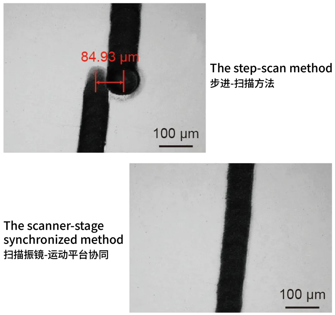
Traditional step-and-scan processing
- Inertia constraint: a large XY stage has high inertia and limited dynamic response;
- Field limitation: if the scanner field is 100 × 100 mm, a 500 × 500 mm part requires 25 tiled regions, and errors appear at boundaries;
- Lack of coordination: the stage and scanner operate as separate systems. The stage moves and settles, and only then does the scanner begin;
- Control distortion: loop delays and dynamic tracking errors cause the real laser path to depart from the commanded geometry.
Solution 1: distortion correction
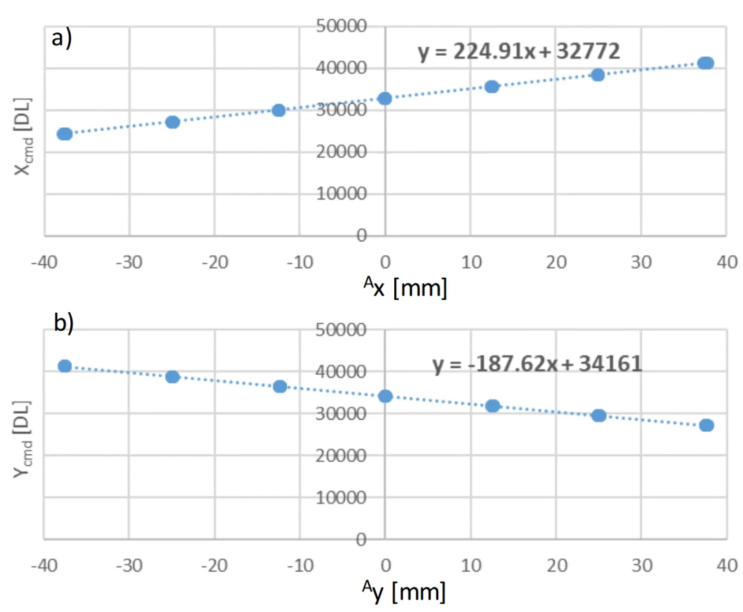
Micrometer-level accuracy requires correction of the system’s geometric distortion.
- Traditional lookup table (LUT): measures thousands of points and stores a compensation map. The process is labor-intensive and accuracy depends strongly on point density;
- Physics-based modeling from sparse data: measures a small grid, for example 5 × 5 = 25 points, and fits an integrated model of system behavior. The model can then calculate compensation anywhere in the field.
Solution 2: Infinite Field of View
Infinite Field of View (IFOV), also called scanner–stage coordination, uses one controller to integrate the galvanometers and XY stage into a cooperative motion system.
Motion-vector decomposition:
- long-distance, smooth, low-frequency motion is assigned to the stage;
- high-dynamic, high-frequency details such as corners and small arcs are assigned to the scanner.
Two broad real-time correction strategies are used:
- Error-prevention approaches, such as those associated with SCANLAB/ACS, use look-ahead trajectory planning to create a path that both stage and scanner can follow;
- Error-correction approaches, such as Aerotech’s, use real-time feedback and let the scanner compensate dynamically for stage tracking error so that the combined position remains accurate.

Solution 3: precise synchronization
Coordination algorithms still require high-fidelity execution and laser triggering.
Direct PWM drive
A conventional controller–drive–motor chain adds delay. Modern systems can send low-level PWM commands directly to the motor stage and receive high-speed position feedback directly, reducing latency and improving response.
Triggering by distance: Position Synchronized Output
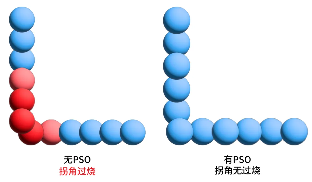
Traditional systems trigger laser pulses at fixed time intervals. When velocity changes, pulse spacing and deposited energy per unit length also change.
Position Synchronized Output (PSO) triggers by traveled distance. For example, the system can fire once every 5 µm. Pulse spacing and spatial energy distribution then remain uniform even when velocity changes, addressing corner overheating at its source.
Advanced power control
Power-correction maps and analog-vector tracking can adjust laser power according to spot position and velocity, keeping deposited energy density approximately constant throughout the process.
The final objective of these techniques is invariance of process parameters. A specified line energy or spot overlap should become the intended physical condition on the workpiece rather than an approximate setting that must be corrected repeatedly through experience.
Conclusion
The galvanometer scanner is evolving from a simple two-dimensional beam deflector into a multi-axis, sensor-rich, highly integrated photonic-processing subsystem.
- Past: a standalone actuator containing motors and mirrors and following an input command;
- Present: an integrated functional unit that can include Z-axis focus control, embedded digital control, and diagnostic data streams;
- Future: a photonic execution node that exchanges data and coordinates deeply with robots, stages, and other intelligent-manufacturing equipment.
Understanding the scanner therefore requires more than mirror speed. The complete engineering picture includes inertia, aperture, optical-field correction, closed-loop sensing, predictive control, coordinated motion, and spatially synchronized laser energy.
References
- Römer, G. R. B. E., & Bechtold, P. “Electro-Optic and Acousto-Optic Laser Beam Scanners.” Physics Procedia, 56, 29–39 (2014). DOI: 10.1016/j.phpro.2014.08.092.
- Cui, M., Lu, L., Zhang, Z., & Guan, Y. “A Laser Scanner–Stage Synchronized System Supporting the Large-Area Precision Polishing of Additive-Manufactured Metallic Surfaces.” Engineering, 7, 1732–1740 (2021). DOI: 10.1016/j.eng.2020.06.028.
- Lane, B., Moylan, S., Yeung, H., Neira, J., & Chavez-Chao, J. Quasi-Static Position Calibration of the Galvanometer Scanner on the Additive Manufacturing Metrology Testbed. National Institute of Standards and Technology, Gaithersburg, MD, 2020, NIST TN 2099.
- Aerotech. Infinite Field of View (IFOV) Synchronizes Linear or Rotary Servo Axes with Laser Scanners.
The Chinese original was published by “Laser Insights” on August 11, 2025, at 07:25 in Chongqing. View the original