Hard chrome was a common repair coating for aerospace manufacturing tools, but hexavalent-chromium hazards, delamination risk, and limited thickness increasingly conflict with green manufacturing and reliability requirements. A study on a ring-shaped 40HM steel tool shows that NiCrBSi laser cladding can create an approximately 2 mm metallurgically bonded repair layer with enough stock for finish grinding.
Aerospace tooling NiCrBSi Hard-chrome replacement Remanufacturing
Avoid hexavalent chromium and reduce blistering, peeling, and rework.
Multilayer deposition supplies finish-machining stock.
Balance height, hardness, dilution, and HAZ depth.
Why replace hard chrome?
Fixtures, rings, and supports used to machine nickel and titanium alloys experience persistent surface wear. Hard-chrome plating restores dimensions and wear resistance but has three major limits:
- Environmental and regulatory risk: chromic-acid systems contain carcinogenic hexavalent chromium and are tightly restricted under regulations such as EU REACH.
- Interface and rework risk: an electroplated layer may blister or peel, and a local failure often requires complete stripping and repeat processing.
- Insufficient machining allowance: plating is usually below 1 mm and may not provide enough stock for dimensional restoration and finish machining.
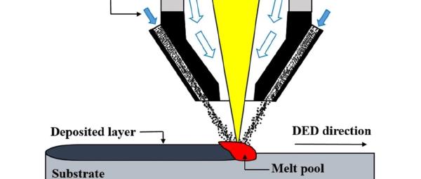
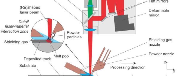
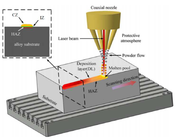
Laser cladding melts metal powder together with a shallow substrate layer to produce a metallurgical bond. It avoids a chromic-acid bath, supports multilayer millimeter-scale buildup, and can use robotic paths and tilted powder delivery on planar, external cylindrical, and internal cylindrical surfaces.
Electrochemical deposition; blistering and peeling possible
Fusion and diffusion create a metallurgical bond
Usually below 1 mm
Approximately 2 mm with multilayer deposition
Hexavalent-chromium solution and waste treatment
Metal powder and no chromic-acid bath
Limited by bath, masking, and deposition uniformity
Programmable robot path and feed orientation
Repair object and material system
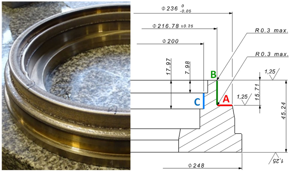
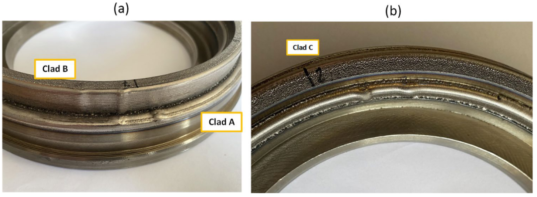
The case concerns a 40HM low-alloy-steel tool used in aerospace-engine manufacturing. Substrate hardness is approximately 28–32 HRC. The repair contains three representative geometries: planar region A, outer cylindrical region B, and inner cylindrical region C.
Substrate: 40HM low-alloy steel
Quenched and tempered 40HM combines strength and wear resistance. It remains sensitive to laser heat: processing must avoid distortion and cracking while limiting deep temper softening in the HAZ.
Coating: NiCrBSi self-fluxing powder
The feedstock is Oerlikon Metco 15F, approximately 15–53 µm, with a Ni matrix and nominal Cr 17%, B 3.5%, Si 4%, C 1%, and Fe 4%.
- B and Si lower melting temperature, improve flow, and reduce unmelted particles.
- Cr and C form hard Cr₇C₃ and Cr₃C₂-type phases for wear resistance.
- The Ni matrix provides toughness and moderates thermal cracking.
The target is at least about 1.5 mm of repair thickness and hardness above 38 HRC. In the demonstrated multilayer process, total buildup is approximately 2 mm so finish machining has adequate allowance.
Equipment, parameters, and geometry
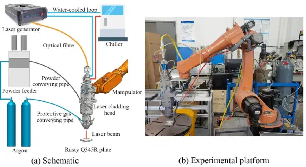
The system combines a Laserline LDF 4000-30 source, GTV PF powder feeder, Fraunhofer IWS coaxial head, Reis RV60-40 robot, and RDK-05 rotary table. Wavelength is 940–980 nm and spot diameter is 3.5 mm.
Laser wavelength
Spot diameter
Travel speed
Target dilution
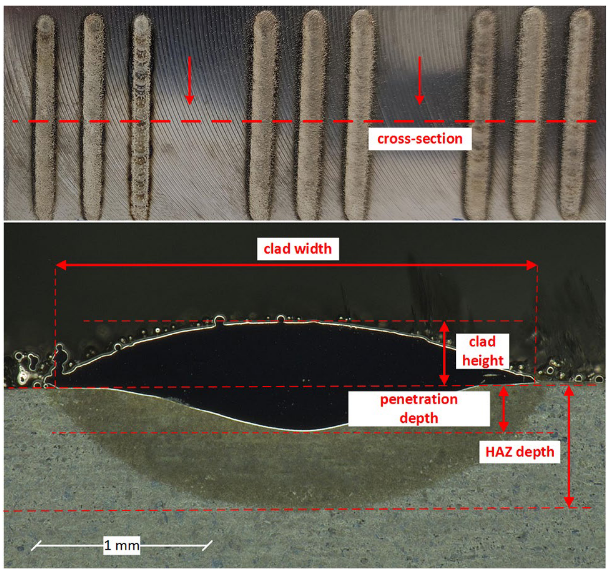
Optimization seeks higher deposit height and hardness while reducing penetration, dilution, and HAZ depth.
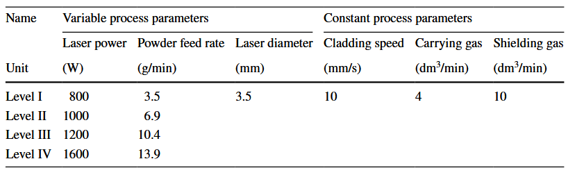
The article reports a selected condition of 1000 W and 17.4 g/min, hardness above 700 HV1, and dilution below 10%. Because the accompanying parameter table ends at 13.9 g/min, reproduction should return to the primary paper and confirm the experimental stage and feeder calibration.
Toolpaths for three surface types
One robot orientation cannot serve all geometries:
- Planar region A: parallel tracks, 50% overlap, and approximately 10° head tilt to reduce powder accumulation over the existing bead.
- Outer cylinder B: helical scanning with synchronized robot and rotary table and approximately 10° tilt.
- Inner cylinder C: about 30° delivery and head orientation in the confined space so the powder cone still intersects the pool.
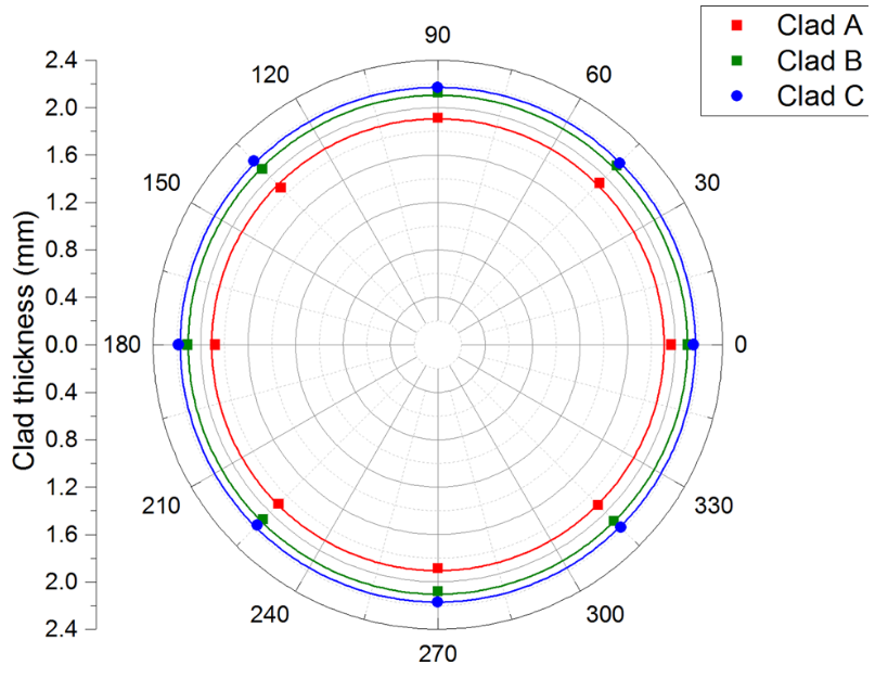
All three regions use two deposited layers for approximately 2 mm total thickness. Additional layers increase thermal cycles and residual stress, so thickness, overlap, and interlayer temperature must be designed together.
Before cladding, the substrate is ground to approximately Ra 1.6 µm or better, oxide and contamination are removed, and isopropanol cleaning is applied. After deposition, planar and outer surfaces can be turned and ground; the internal cylinder needs a dedicated milling strategy.
How parameters change the layer
Laser power: dilution is the principal cost
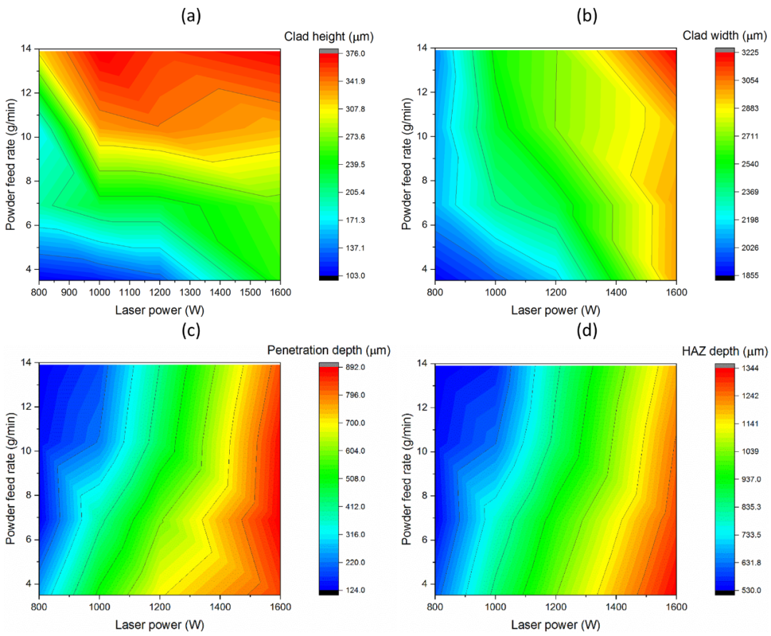
Higher power enlarges the pool and melts more substrate. The bead may widen, but penetration and HAZ depth also increase. Above roughly 20% dilution, substantial Fe enters the NiCrBSi layer, creates Fe–Cr solid solution, and weakens hard-phase reinforcement.
Hardness and dilution must be read together
At 1000 W and 10.4 g/min, peak hardness is about 680 HV0.3 and dilution about 10%. Low dilution preserves Cr₇C₃, Cr₃C₂, and other hard phases; higher dilution changes chemistry and phase balance.
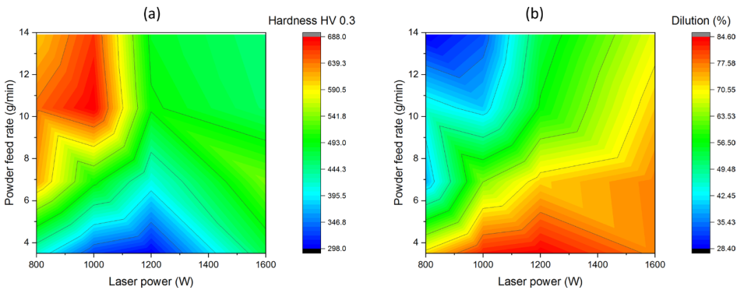
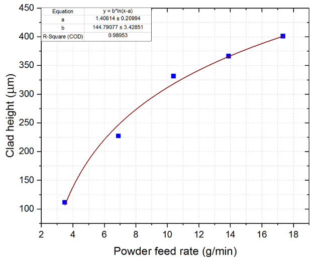
Above approximately 17.4 g/min, unmelted particles may increase. A valid window must be defined by cross-sectional geometry, dilution, hardness, and defects rather than deposit height alone.
Multilayer strategy: thickness as machining stock
Fifty-percent overlap and two layers produce about 2 mm on planar, external, and internal surfaces. HAZ depth should remain near or below 200 µm to avoid excessive substrate softening.
Post-machining: the second challenge
Repair is incomplete until the part returns to dimensional and roughness tolerance. A layer near 750 HV1 imposes a high cutting load.
Grinding is the most stable route
Grinding removes small increments with low impact. A 0.4 mm grinding depth produced no observed cracks and a final Ra of 0.272 µm, better than the aerospace-tool requirement of Ra 1.25 µm.
Turning and milling require new tooling and vibration control
During outer-cylinder turning, a carbide insert chipped after approximately 0.3 mm of cutting. Internal-cylinder milling produced local coating cracks, indicating coupling between residual stress and cutting vibration.
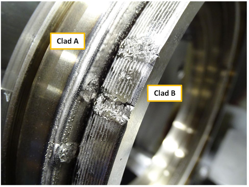
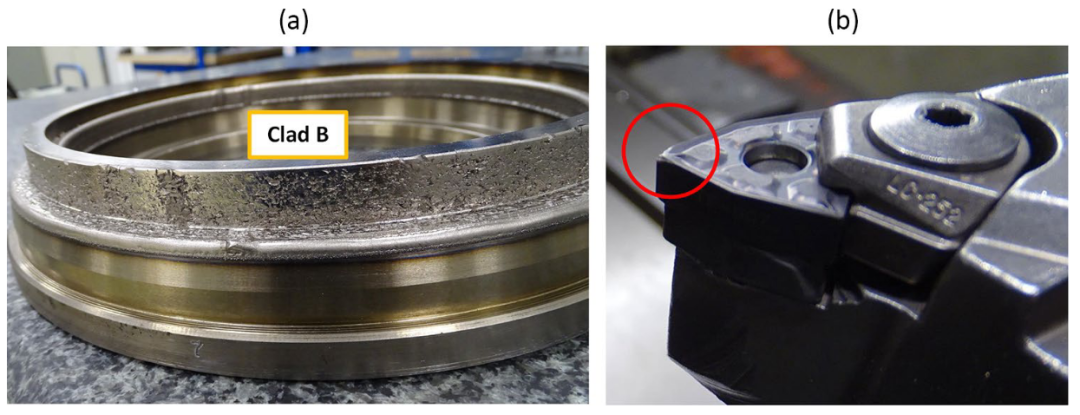
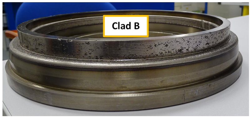
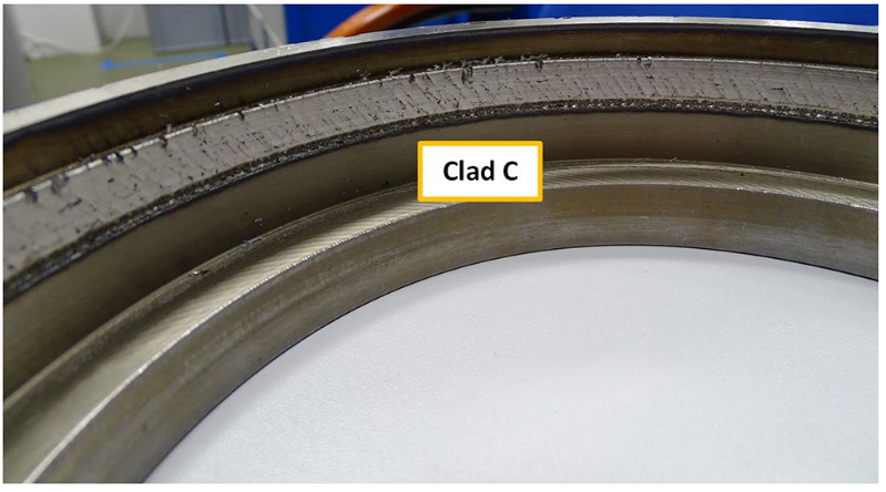
Turning should evaluate CBN or diamond-coated tools and cooling to reduce thermal loading. Milling should reduce feed per tooth and use a high-speed, low-vibration strategy.
Interface structure and hardness gradient
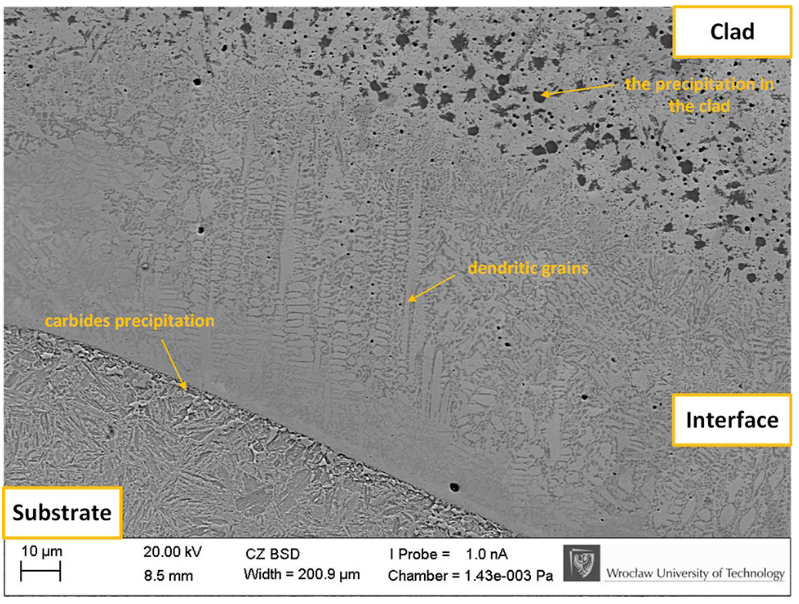
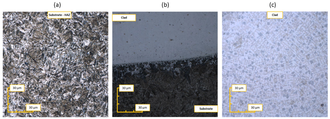
SEM shows a continuous transition between the NiCrBSi layer and 40HM substrate without obvious pores or cracks. Ni and Cr diffuse into the steel and form an approximately 5 µm interdiffusion zone.
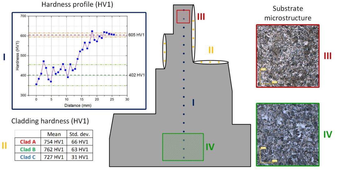
Rapid cooling forms lath martensite in 40HM near the interface, while the far field remains predominantly tempered martensite. Hardness changes from 754–762 HV1 in the clad to about 605 HV1 in the near-interface substrate and approximately 402 HV1 farther away.
Engineering conclusions
Hard-chrome replacement is not about maximizing thickness or hardness. The repair layer must be machinable, low-dilution, low-defect, and must not excessively soften or distort the substrate.
A practical development route is:
- use single-bead trials to keep dilution near or below 10%;
- work backward from final geometry and retain approximately 0.3–0.5 mm grinding stock after multilayer deposition;
- grind, degrease, and, in humid conditions, pre-dry the powder;
- design finish machining as part of the repair, with grinding preferred and turning or milling separately qualified;
- add path transitions and powder-flow control at internal surfaces and start/stop regions.
Source material
- Koruba, P., Pawlicki, M., Mróz, A. et al. Feasibility of laser cladding for tooling repair in aerospace manufacturing: an alternative to chrome plating. Archives of Civil and Mechanical Engineering, 25, 52 (2025).
- DOI: 10.1007/s43452-024-01110-5
This page is intended for technical study; application should follow the primary paper, material specifications, and component-level validation.