Dynamic beam shaping adds a new control variable to directed energy deposition: the spatial distribution of laser power can change during the build. By modifying the local thermal cycle, a deformable mirror can reshape the melt pool and alter grain morphology and crystallographic texture without changing nominal power, speed, or powder feed.
Dynamic beam shaping Deformable mirrors Power-density distribution Microstructure
Laser cladding, directed energy deposition, direct energy deposition, direct metal deposition, and laser metal deposition describe closely related process principles, although terminology varies by application.
Application background
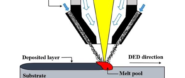
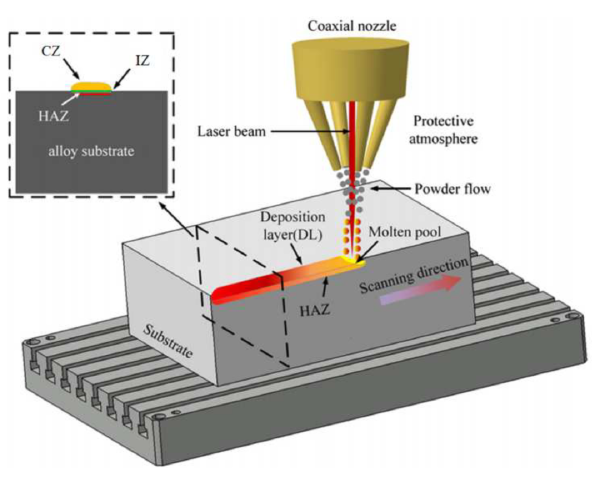
Directed Energy Deposition (DED) feeds powder or wire directly into a melt pool while a heat source and nozzle move together. When the heat source is a laser, the process is often called DED-L. Unlike powder-bed fusion, it can build on an existing surface and is not confined to a powder-bed footprint.
Key advantages include:
- manufacturing large components with relatively few envelope constraints;
- repairing high-value turbine blades, dies, and other damaged parts;
- adding new geometry or functionality to an existing component.
The challenge is a tightly coupled material–process chain:
- final strength, toughness, fatigue resistance, and anisotropy depend on grain size, shape, and orientation;
- those microstructures are set by heating, melting, cooling, and reheating during deposition;
- conventional controls—power, speed, and feed rate—change the entire process and provide limited local freedom.
The power-density distribution (PDD), or beam shape, controls where energy enters the pool and therefore changes thermal gradient, cooling rate, and solidification. Most machines use a fixed Gaussian or top-hat spot. A dynamically variable PDD adds a much more direct local thermal-control axis.
Redistributes energy within the focal plane.
Changes gradients, cooling, and reheating.
Controls grain size, morphology, orientation, and texture.
Beam-shaping approaches
Beam shaping changes the focal-plane intensity distribution beyond a circular Gaussian or uniform top-hat.
Static shaping
Diffractive optical elements, specialty fibers, and freeform mirrors can generate fixed annular, square, or line-shaped fields. They may improve uniformity or target a particular structure, but their shape cannot change during deposition.
Dynamic shaping
Several technologies can vary the distribution during processing:
- Galvanometer scanning: a small spot traces a larger virtual shape. If scanning is not fast enough relative to the thermal response, energy is deposited discretely and local peak temperature can become excessive.
- Coherent beam combining: flexible but optically and electronically complex and dependent on a suitable source.
- Multi-plane light conversion: useful but with a limited adjustable space for some high-power applications.
- Deformable mirrors: actuators change mirror shape, controlling reflected wavefront and therefore focal-plane PDD. Millisecond response, continuous illumination of the entire shaped footprint, and high flexibility make this approach attractive for DED.
Experimental system and method
Laser and optical path
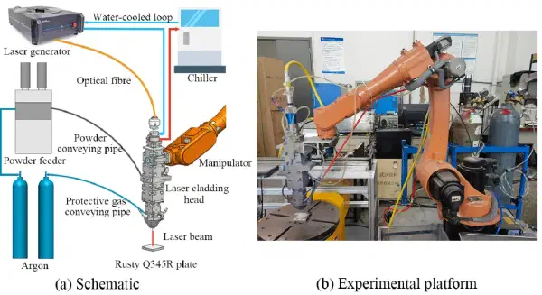
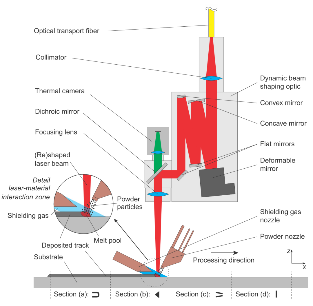
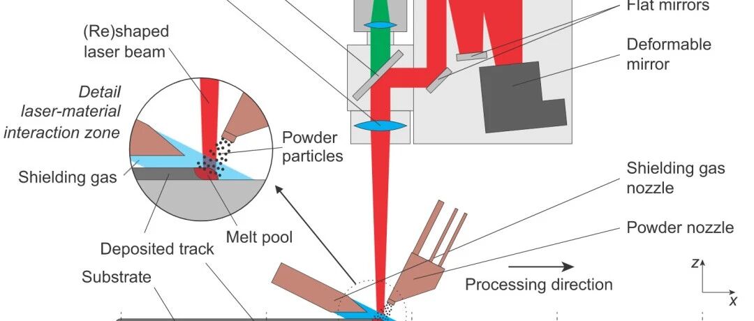
The experiment uses a 10 kW Yb:YAG disk laser, a 100 µm delivery fiber, a 150 mm collimator, and a 300 mm focusing optic.
The dynamic shaper is located between the collimator and a dichroic mirror, where it acts on a collimated beam. Its main components are:
- a piezoelectric PDM30-37 deformable mirror whose actuators control the reflected wavefront;
- a Galilean beam reducer that matches the beam diameter to the mirror and focusing optics;
- two flat steering mirrors.
The deformable mirror changes state in approximately 10 ms, fast enough for in-process switching. With no actuator drive, the flat mirror produces an approximately 0.8 mm top-hat spot at focus.
Material and fixed process parameters
250 × 100 × 10 mm³
Oerlikon Metco 41C
Argon shielding
Powder feed 7.0 g/min
Three 220 mm single tracks were produced. Each was divided into four 55 mm segments, one for each PDD, and the experiment was repeated three times.
Four beam shapes
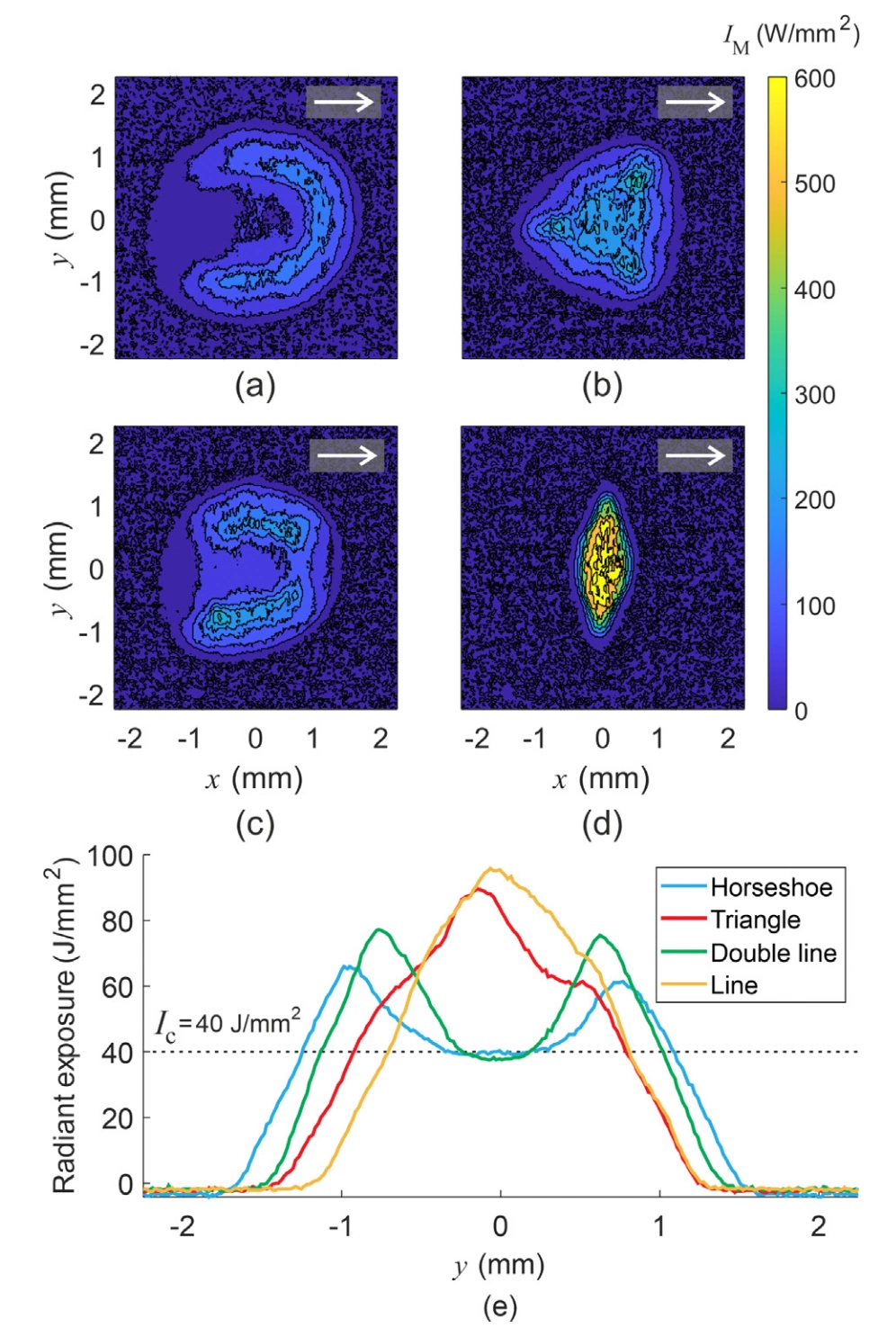
The selected PDDs were horseshoe, triangle, double line, and line. They were intentionally very different to create clearly distinguishable melt-pool behavior. All were approximately 3 mm wide in \(y\), while their length and concentrated-energy regions differed in \(x\). The single-line field was shortest at about 0.7 mm.
Areal energy-density description
For a noncircular, nonuniform field, simple quantities such as \(P/(vd)\) or \(P/(vw)\) lose the spatial distribution. The paper defines
\[ H_e(y)=\frac{\int I(x,y)\,\mathrm{d}x}{v}, \]which gives the total energy received per unit area at a transverse location \(y\) as the distribution passes in the \(x\) direction. This directly links the optical field to melt-pool width and cross-sectional temperature: a centrally weighted profile should deepen the center, whereas edge-weighted energy should broaden the pool.
Results and discussion
Melt-pool morphology
The PDD changes both pool size and trailing-edge shape:
- the horseshoe produces the widest pool, consistent with high energy at its sides;
- the horseshoe and double line produce a concave tail, meaning the center freezes before the sides;
- the triangle and line produce narrower pools and a convex tail, with the edges freezing before the center.
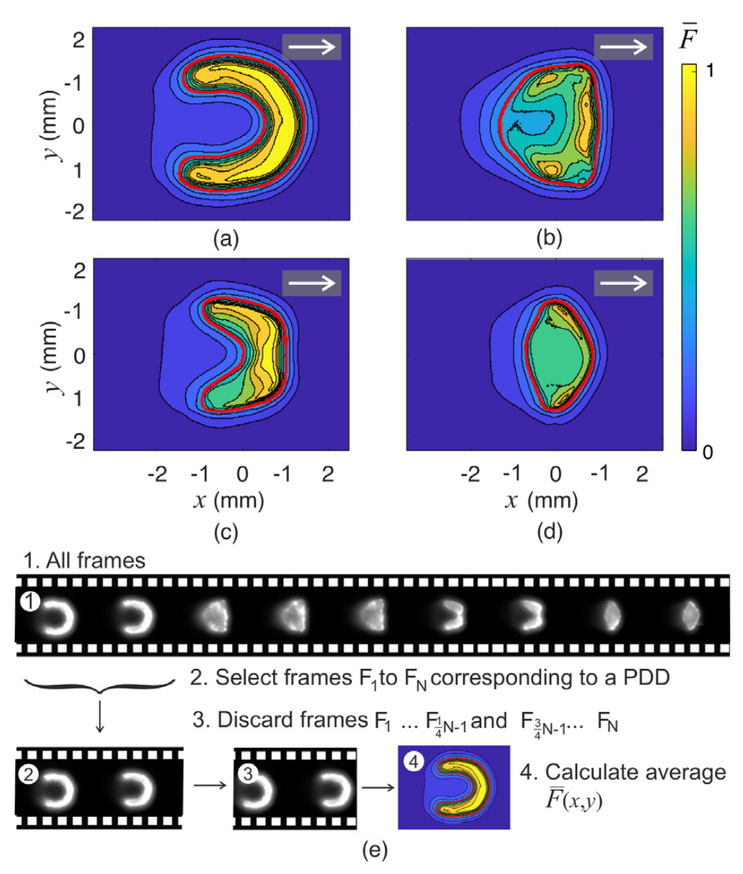
The tail outlines the solidification front and dominant heat-flow direction. A concave tail encourages columnar growth from both sides toward the center; a convex tail changes the direction and convergence of the growing grains.
Microstructure and texture
Electron backscatter diffraction reveals distinct top-view structures:
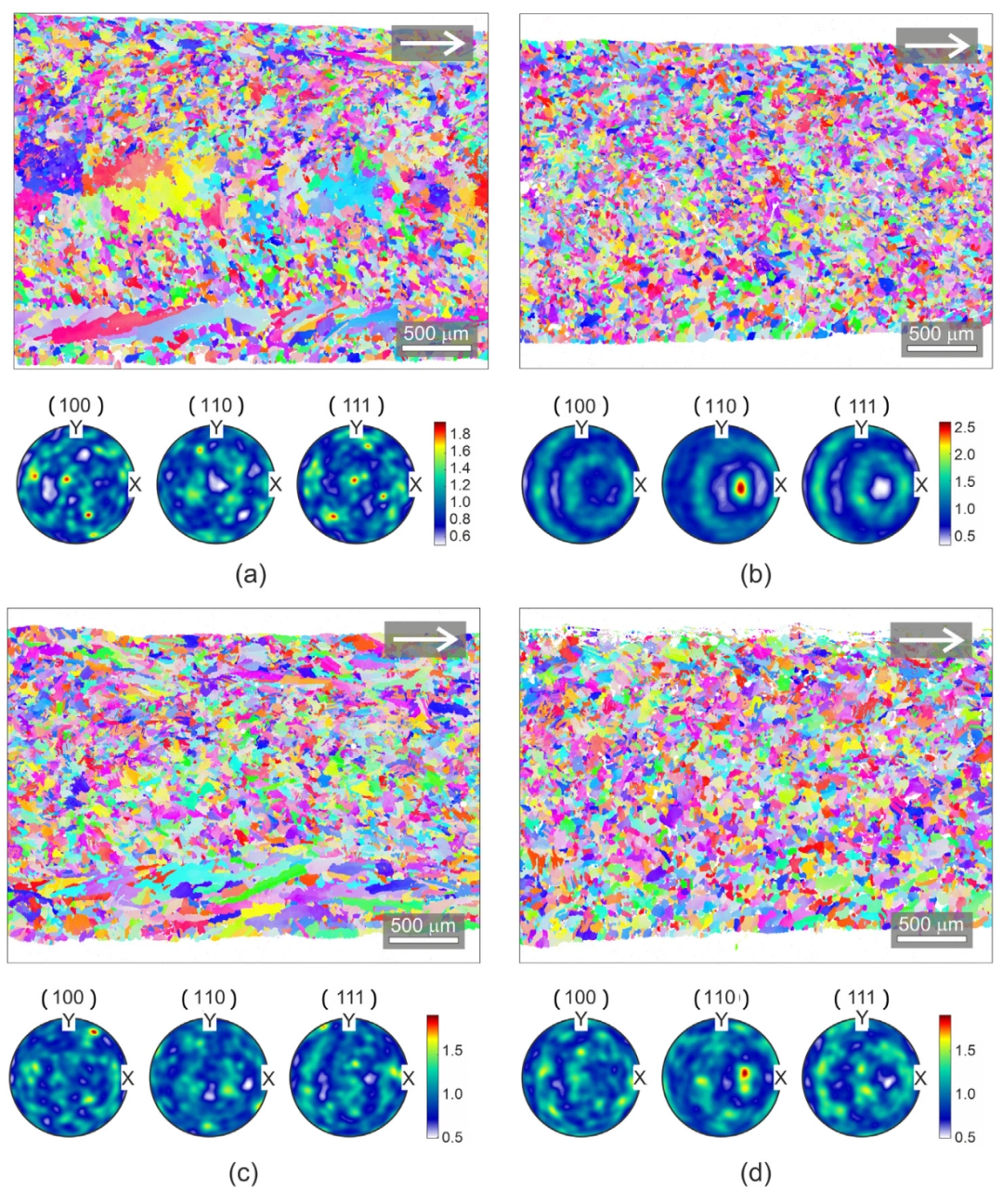
- Horseshoe: large equiaxed grains in the center, elongated columnar grains at the sides, and smaller equiaxed grains in transition regions; weak texture.
- Triangle: mainly fine equiaxed grains with a very strong preferred orientation.
- Double line: side columnar grains and central equiaxed grains, without the large central grains of the horseshoe; weak texture.
- Line: mainly equiaxed grains and intermediate texture strength.
Fine equiaxed structures generally support a more isotropic strength–toughness balance. Strong texture produces anisotropic mechanical response. The experiment therefore demonstrates that PDD can control not only grain shape but texture intensity.
Cross-sectional EBSD shows the evolution from substrate to top surface:
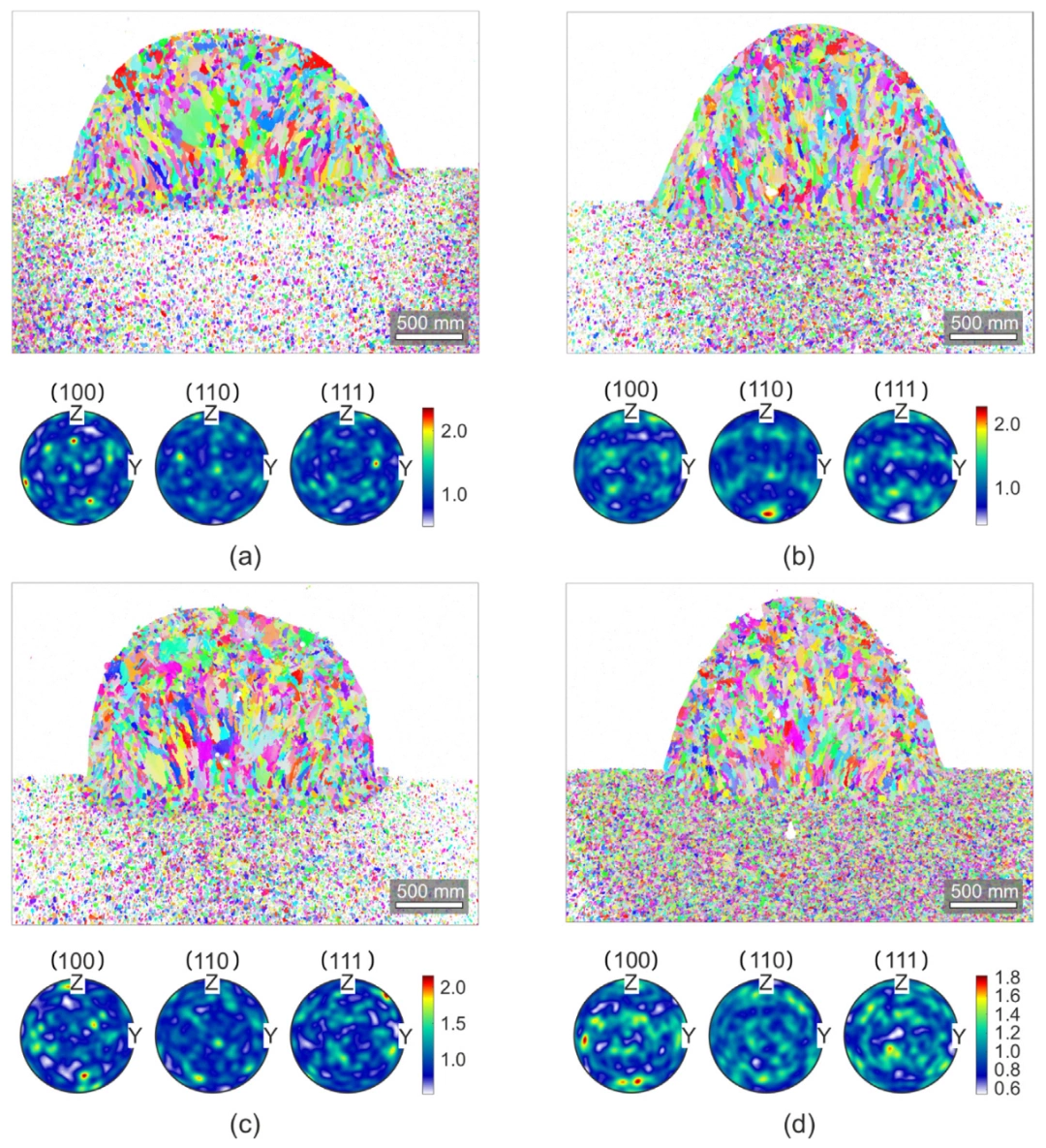
- Horseshoe: epitaxial columnar grains at the bottom and large equiaxed grains in the center and top.
- Triangle: relatively consistent equiaxed or slightly elongated grains through the height, with a clear (110) texture.
- Double line: columnar grains at the bottom and larger equiaxed grains above.
- Line: bottom epitaxy followed by predominantly equiaxed upper grains.
Columnar grains follow the maximum temperature gradient, approximately normal to the pool boundary. Equiaxed grains form where undercooling ahead of the front is sufficient or where the gradient is relatively low near the pool center.
Control chain
Redistribute focal-plane energy.
Change width and tail geometry.
Change gradient and solidification rate.
\(G/R\) affects morphology; \(G\cdot R\) affects scale.
The full causal sequence is therefore PDD → melt pool → thermal field → microstructure and texture.
Engineering implications
- Inverse design: how can a target grain morphology or texture be converted into a specific PDD?
- Cost and integration: high-power deformable mirrors and control systems are expensive and must be integrated optically and electronically with existing DED equipment.
- Multitrack and multilayer behavior: the paper studies single tracks. Overlap, reheating, and interlayer thermal interaction may modify or erase the single-track effect.
Reference
- Bremer, S. J. L., Luckabauer, M., Aarts, R. G. K. M., et al. “Dynamic laser beam shaping by means of a deformable mirror to tailor microstructure in Directed Energy Deposition.” Journal of Materials Processing Technology, 339 (2025), 118797. DOI: 10.1016/j.jmatprotec.2025.118797.
The original Chinese edition was published by “Laser Insights” in Chongqing on May 5, 2025, at 22:20. View the original post